
Links Menu

The Lock Icon is different in the simulation. Locking an object makes it invulnerable to any external force.
Joints Group
A joint is something like a hinge, which is used to connect two solids. It is a relationship that is enforced
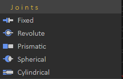
between two bodies so that they can only have certain positions and orientations relative to each other. To create a joint between two solids, choose the joint type from the Links Menu, the joint will be added to the Links Tree, and its properties will appear in the Properties Panel on the left.
- Fixed: Maintains a fixed relative position and orientation between two solids, in practice, using this joint is rare. If two bodies are needed to be glued together, it is better to represent them as a single solid when deciding that both of the solids hold the same properties during the simulation session.
- Revolute: Also called pin joint, is a one-degree-of-freedom kinematics pair used in mechanisms. Revolute joints provide a single-axis rotation function used in many places such as door hinges, folding mechanisms, and other uni-axial rotation devices.
- Prismatic: Also called slider joint, provides a linear sliding movement between two bodies. The two joined solids have their rotation held fixed relative to each other, and they can only move along a specified axis, chosen by the user while specifying the joint properties.
- Spherical: Also called a ball and socket joint, is a joint in which the ball-shaped surface of a solid fits into the cup-like indentation of another solid. This type of joint allows the solid to move at a 360-degree angle—with more freedom than other joints.
- Cylindrical: A two-degrees-of-freedom kinematics pair used in mechanisms. Cylindrical joints provide a single-axis sliding function as well as a single-axis rotation, providing a way for two rigid bodies to translate and rotate freely.
A selected Joint requires its properties to be set in order to work appropriately.
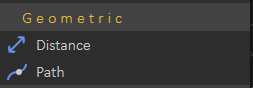
Geometric Group
The Geometric group is concerned with shape, size, the relative position of solids, and the properties of 3D space. Considers questions of relative position or spatial relationship of geometric figures and shapes.
- Distance: Creates a link between two solids based on maintaining a certain distance between them at all times during the simulation.

- Path: Specify a path in the scene for the solid to follow during the simulation
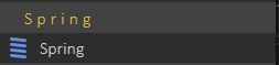
Spring Group
Creates a spring link between two points that the user selects. A spring is an elastic object used to store mechanical energy. The user needs to input the properties of the spring in the Properties dialog, Spring Constant, Damping, and Resting Length in order to work properly.
 Check this tutorial for more about spring creation and simulation.
Force/Torque Group
A user can affect the behavior of a certain solid by applying an external force or torque on it.
- Force: Applies an influence (push or pull) that tends to change the motion of an object
including to begin moving from a state of rest, i.e. to accelerate. In other words, a force can cause an object with mass to change its velocity. A force has both magnitude and direction.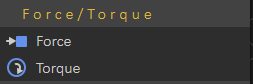
- Torque: applies an influence that produces a change in the rotational speed of an object.

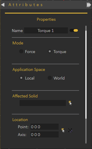
- Name: Where the user specifies a name for the new force or torque.
- Mode: This section allows the user to change between force and torque modes.
- Application Space: The user specifies whether the force or torque will follow the affected solid as it moves (Local), or stay static on the original point of application (World).
- Affected Solid: Where the user selects the affected solid.
- Location: Where the user selects the application point and axis for force or torque, in addition to that the ability to flip the force or torque direction.
- Magnitude Function: This edit button, if clicked, displays the Function Editor dialog box where the user specifies and selects the desired magnitude function for force or torque.

- Motion Function: Constant, Ramp, 3-4-5 Polynomial, Polynomial, Sine, Derivative, Integration, or Sequence.
- Constant.
- Ramp: Initial Value and Slope.
- 3-4-5 Polynomial: Amount of Displacement and Duration of Motion.
- Polynomial: C0, C1, C2, C3, C4, and C5.
- Sine: Amplitude, Phase, and Frequency.
- Derivative: Choose Function.
- Integration: Choose Function, Constant (C0), Lower Limit (X1), and Upper Limit (X2).
- Sequence: Select Sequence.

Gears Group
Gears group is located on the Links menu. You find two buttons in this group, as shown in the image. A brief description of each button, supported by the SimLab Composer's simulation engine, is given as follows:
- Gear (Gear Train or Transmission): Two or more gears working in a sequence. Such gear arrangements can produce a mechanical advantage through a gear ratio and thus may be considered a simple machine. Geared devices can change the speed, torque, and direction of a power source. The most common situation is for a gear to mesh with another gear.
- Rack and Pinion: A gear can also mesh with a non-rotating toothed part, called a rack, thereby producing translation instead of rotation. A rack is a toothed bar or rod that can be thought of as a sector gear with an infinitely large radius of curvature. Torque can be converted to linear force by meshing a rack with a pinion: the pinion turns; the rack moves in a straight line. Such a mechanism is used in automobiles to convert the rotation of the steering wheel into the left-to-right motion of the tie rod(s). Racks also feature in the theory of gear geometry, where, for instance, the tooth shape of an interchangeable set of gears may be specified for the rack (infinite radius), and the tooth shapes for gears of particular actual radii are then derived from that. The rack and pinion gear type is employed in a rack railway.
Pulley Group

- Pulley: A pulley may also be called a sheave or drum and may have a groove between two flanges around its circumference. The drive element of a pulley system can be a rope, cable, belt, or chain that runs over the pulley inside the groove.
No Comments