
Common Toolbar
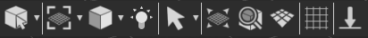
Common Toolbar is located in the lower part of the 3D area on top of the Library, it is always accessible to the user and it includes the following:
Select Object
The Default Pick mode in SimLab Composer/Studio returns the location and the normal direction at the selection point. The geometry at the picked location will be selected in the Object Tree, and its bounding box will be displayed in the 3D area.
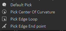
To get more precise picking the user can change selection to:
Center of Curvature: To select center of a circle or arc
Edge Loop: To select center of a closed loop, like center of one of the faces of a cube
Edge End Point: To select the closest end of an edge
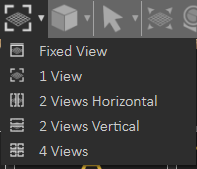
Window Configuration
By default the user views 1 view in the 3D area, which covers all available space, this configuration allows the user to switch to 2 or 4 views. Different views can help the user better arrange elements in the scene.
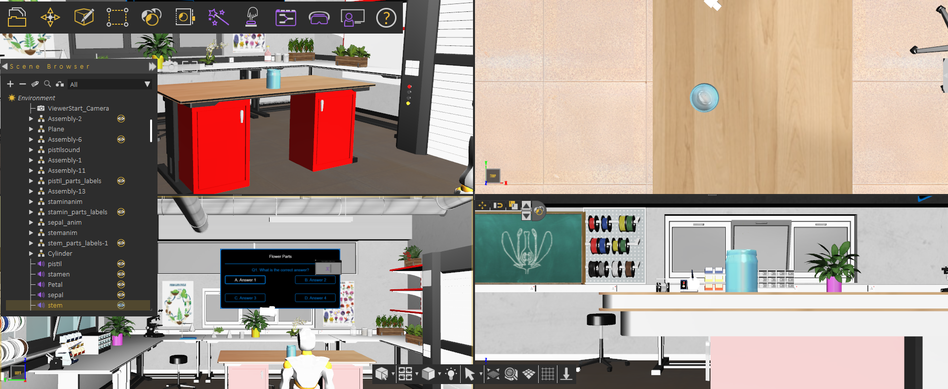
The following image shows switching Window Configuration to 4 views:
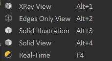
View Mode
The default view mode in SimLab Composer/Studio is the Solid View, which displays solid models with edges hidden. The user can change the view mode to any of the available modes from this menu.
1. XRay View: Gives x-ray effect to the models in the scene.
2. Edges Only View: Displays only the edges of the models in the scene.
3. Solid Illustration: Displays models in solid view, with their edges illustrated.
4. Solid View: Displays models in shaded solid view.
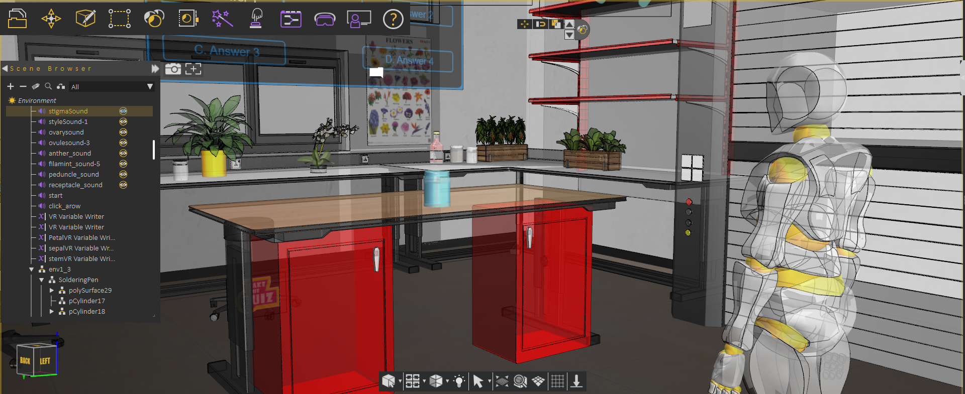
The following image shows a scene in XRay View:
Light On/Off
This option allows the user to turn off the default camera light in SimLab Composer/Studio to get a view better matching what the user will see in VR Viewer, or to only see lights coming from created artificial light sources (the ones found in the "Create" menu from the main toolbar).
View Behavior
Default view behavior
The mouse behavior will be as shown in the table below:
| Navigation | Mouse Button |
| Pan | Middle mouse button |
| Rotate | Left mouse button |
| Zoom | Right mouse button |
Camera Pan
Changes the behavior of the left mouse button, to Pan.
Camera Zoom
Changes the behavior of the left mouse button, to Zoom.
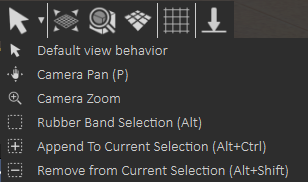
Rubber band
This function changes the selection mode in the 3D area and it has three options:
Rubber Band Selection: Changes the selection icon to a square band, allowing the user to window select more than one geometry in the 3D area.
Append To Current Selection: The selection icon will show a ‘+’ sign inside the square band. The user can window select more geometry in a different section of the 3D scene, without losing the previous selections.
Remove from Current Selection: With a ‘-‘ sign added to the band, the user can remove geometry form selection, without losing previous selections.
Fit all
Updates camera to fit all geometry in the scene within the active view area.
Zoom to Object
Updates the camera in the active viewport, to zoom to the selected object. In case the user presses the button without selecting an object, a message will be displayed on top of the Common Toolbar asking him to do so.
Switch Between Parallel and Perspective Views
Switches the camera between perspective and parallel modes, in the active viewport. For engineers who are used to parallel mode, this option would be helpful.
Capture View image
Captures an image for the current view from the scene, and opens a dialog to save it.
No Comments