Geometry Menu
Break Group
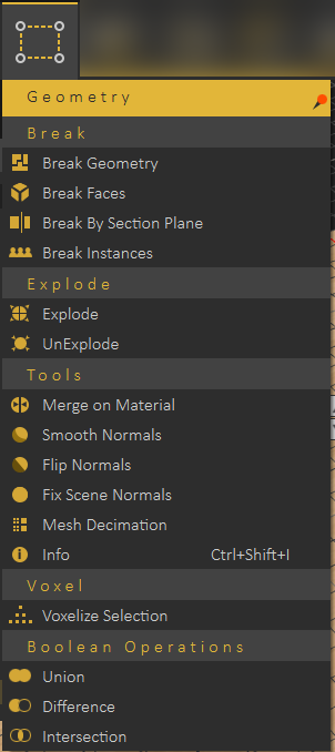
Break Geometry
The smallest representation of geometry in SimLab VR Studio is 3D Geom, which is a geometry that has one transform and one material applied to it. All contents of 3D Geom are moved together, and have the same material.
Some model formats do not support saving Scene Browser structure, so when importing 3D models of those formats, 3D Geom can contain many none connected parts. The Break Geometry tool enables the user to break a 3D Geom that contains none connected parts into multiple 3D Geoms. Each one of the new 3D Geoms can be moved separately and can be assigned a unique material.
Break Faces
In case the Break Geometry tool fails, Break Faces will break the selected 3D model into its faces. Each face will be converted to 3D Geom, and added to the Scene Browser. Unique materials can be assigned to each face.
Break by Section Plane
A section plane should be created first in the scene, using Section Plane function in the Create menu. This function requires/enables the user to select the geometry to cut through. Using the same section plane with different orientations, different cuts can be done on the geometry.
Break Instances
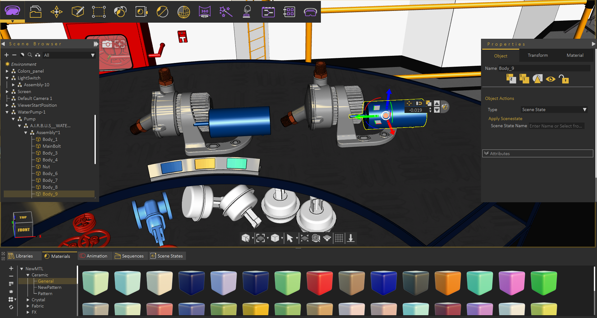
Instances in SimLab VR Studio are multiple duplicates of an object using the same materials structure, and same transforms as the original object. Instances are created by selecting an object then clicking Ctrl+t. In the below image a second water pump was created as an instance of the original one, thus they share the same material.
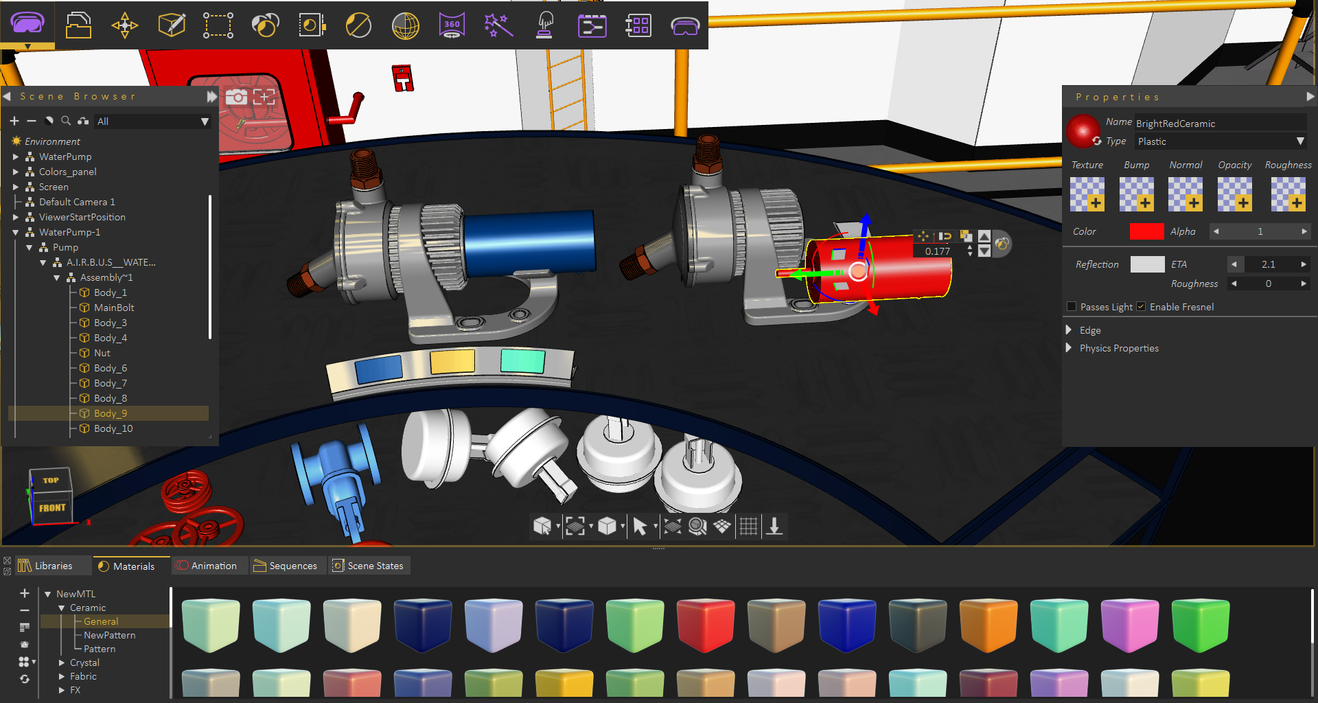
Using Break Instances each pump can now have its own materials/transforms.
Explode Group
Explode / UnExplode
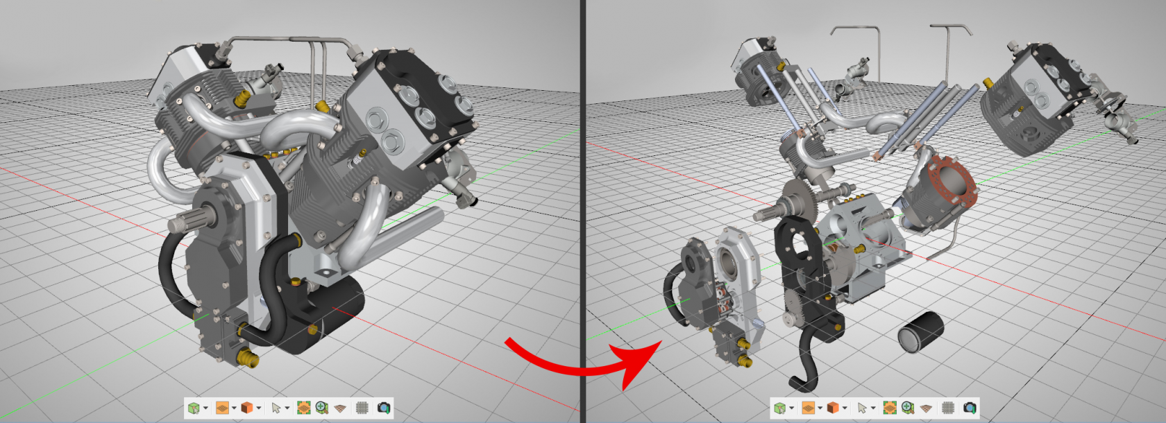
Can be used to show the components of an assembly. Selecting it will show geometry draggers, allowing the user to move (explode) the selected object(s) in the X, Y, and Z directions. The user can also rotate the dragger to select an arbitrary vector to be used for exploding the assembly. Check this tutorial for more about Explode function.
The user should click either the Approve or the Decline mark in In the central part of 3D area, when done with exploding the geometry. Clicking the red Decline mark will cancel the operation of creating the exploded view. After completing the explode operation the user can go back to the original model by selecting UnExplode.
Tools Group
Merge on Material
With an assembly selected in the 3D area, selecting this tool will merge geometry using the same material into a single geometry.
Smooth Normals
This tool can be used to average the normals of the geometry to appear smoother during rendering. Also vertices having the same position and normal direction will be replaced by a single vertex, thus reduce the size and complexity of a 3D model.
Flip Normals
Clicking this tool will have the selected objects' normals flipped.
Fix Scene Normal
Generates appropriate normals for the selected geometry.
Mesh Decimation
Reduces the number of polygons in the selected geometry without affecting its appearance greatly.
The following tutorial shows Mesh Decimation in action, The tool can be very helpful if you need to run VR experience on memory limited devices
Info
Clicking this tool will display Geometrical Info dialog, showing the number of objects, vertices, and polygons in the selected geometry. Knowing the number of vertices and polygons can help a user estimate the size of the output file. This might make the user ignore some details, for sharing efficiency. Shortcut (Ctrl + Shift + I)
Voxel Group
Voxelize Selection
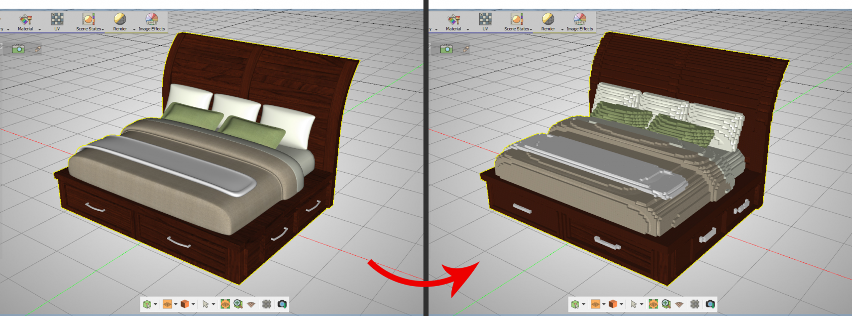
Voxelizing a 3D model is rebuilding the 3D model using building blocks (voxels), like LEGO. The user can choose the building block to use for voxelization, and can choose to voxelize the whole scene, or the selected geometry. Notice that this will add a significant number of polygons to the 3D scene.
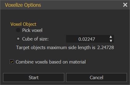
The Voxelize Options dialog will open, when selecting this options. The default voxel object is a cube of certain size, and the user can choose a different object shape, by clicking the Pick voxel option. The voxel object needs to be a geometry in the scene, and the user can just pick it.
The Combine voxels based on material option, if checked, will combine all voxels, based on material, each in one geometry in the Scene Browser.
If not checked each voxel will have its own geometry in the Scene Browser.
To Voxelize any 3d model, follow the steps below:
- First, export 3D model from any 3d software as one of the Supported Import Formats in Composer/ Studio
- Import your model to Studio, click File → Import, or by using Ctrl+I, then select your model format and click Open.
- Select the 3D model in SimLab VR Studio and click on Geometry → Voxelize Selection. The Voxelize Options dialog will appear, where the default voxel object is a cube of certain size. The smaller the size of the voxel the larger the size of the output file. The user can choose a different object by clicking the Pick voxel option then select another small object eg, Sphere, Cylinder or any object in the scene, then click Start.
- When the convert operation is complete, the new object will be added to the Scene Browser.
Boolean Operations Group
Boolean Operations
Boolean operations are smart tools that ease the process of performing simple modeling tasks in SimLab VR Studio and without the need to go back to the CAD design application.
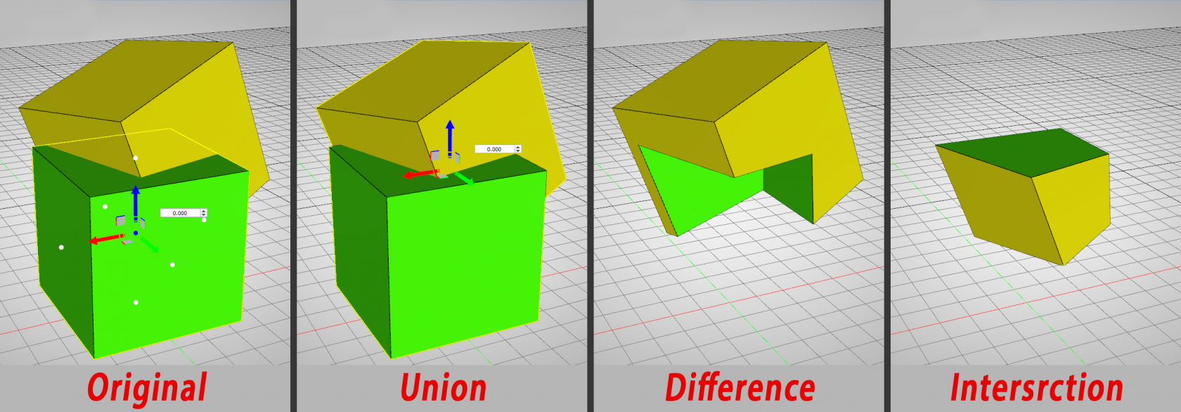
- Union: Removes the intersecting part of two objects or set of objects, and preserves the remaining as one.
- Difference: Deducts the shape and volume of one object or set of objects from another object or set of objects. So it's like the first 3D object minus the second.
- Intersection: Preserves the intersecting part of two objects or set of objects, and removes the rest.

No Comments