Create Menu
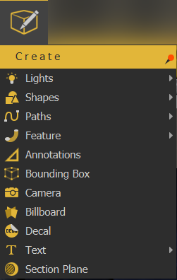
Enables the user to create different scene elements that can add value to 3D scenes.
Lights
Light sources in SimLab VR Studio:
Point Light
Creates a spherical Light Source geometry and adds it to the scene. Point lights can be moved and positioned, using any of the move draggers.
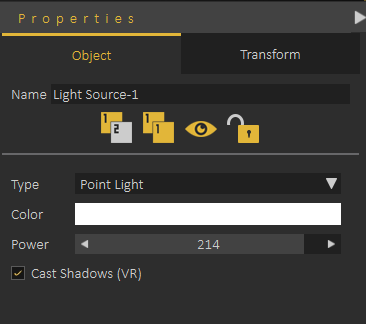
The light properties can be found in the Properties Panel, to the right of the 3D area. There, the user can edit the light properties, like changing its color, or its power. The following image shows properties of the point light.
Area Light
Depending on the effect the user needs, this is another light type that can be used. Same as Point light, area lights have parameters that the user can change in the Properties Panel.
Spot Light
In addition to the main light properties, spot light has blend property that reduces the sharpness of the spot light making it blend with the environment. It also has Cone Angle property that sets the angle of the light.
Directional Light
Directional lights are for exterior scenes. The user can change the direction of the light but not its location. Other parameters for this light include, light color, light power, and light name.
IES Light
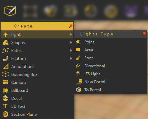
IES Lights describe light distribution, the user can create an IES light from the Create -> Lights menu or from the Library -> Lighting Settings -> IES Light as shown in the image below
Shapes
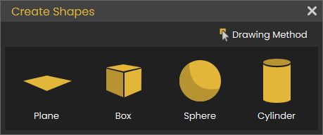
The shapes are Plane, Box, Sphere and Cylinder;
First the user needs to select the method for creating the 3D shape as follows:
Draw on Object
This way is useful when the object is rotated and an object needs to be added on it. Check this tutorial to learn more about this function.
Draw on Grid
Creates 3D shapes based on the size of the grid dimensions. Select the plane to draw the 3D shape on, then select the shape. Check this tutorial to learn more about this function.
Draw by Dimensions
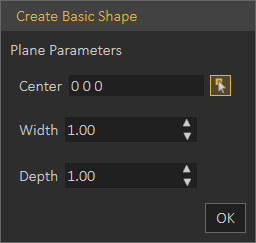
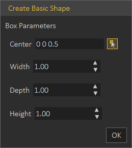
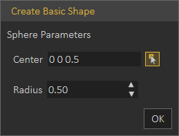
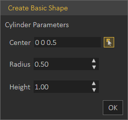
The user needs to input coordinates/dimensions for the shape to draw in the Create Basic Shape dialog as shown below:
Plane: Creates a 2D Plane, in Center field, coordinates are entered. Width and Depth values determine the size of the created plane.
Box: Creates a 3D Box, in Center field, coordinates are entered. Width, Depth, and Height determine the size of the created box.
Sphere: Creates a 3D sphere, in Center field, coordinates are entered. Radius determines the size of the created sphere.
Cylinder: Creates a 3D Cylinder, in Center field, coordinates are entered. Radius and Height determine the size of the created cylinder.
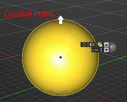
After creating a basic shape, selecting the shape will show its Control Points which appear in white. Picking on one of these points will change it into an arrow that can be pulled to update the size of the basic shape, as shown in the image below.
Paths
Create Path
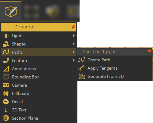
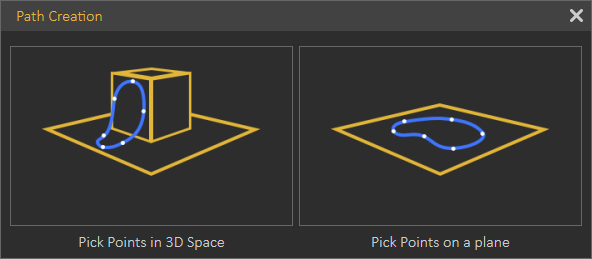
Paths created in SimLab Composer/Studio can be from points in 3D space or on a plane. So when clicking the Create Path option, the Path Creation dialog will open, for the user to pick 3D or planer path.
Picking points in 3D space will create a path that is not on one plane. This can be useful to create a path for geometry to follow, or path for camera.
Picking points on a plane, requires specifying the plane to create the path on. The path and all selected points will be on this plane.
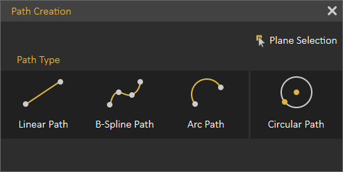
Both path creation options will open the Path Creation dialog shown below, where the user can create different types of paths.
The user can select Linear Path, B-Spline Path, Arc Path, or switch between the types to have a line segment for example following a B-Spline Path.
Paths can be open or closed, clicking on the first point in the path will close the path.
Apply Tangents
One of the points of a created path should be selected, before choosing this option. The program will ask for picking a point and normal to determine the tangent. So picking a point will modify the location of the picked path point to become tangent to the selected point.
Generate From 2D
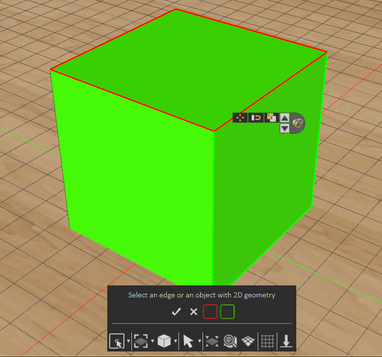
Creates 2D path from the outline of a selected surface. Using the Select options from the Common Tool bar can help in selecting a face, like selecting Pick Edge Loop, as shown in the image below.
Feature
Features created in SimLab Composer/Studio allow the user to perform basic modifications and improvements to 3D models in order to improve the realism of the 3D scene without needing to revert to a CAD application.
Sweep
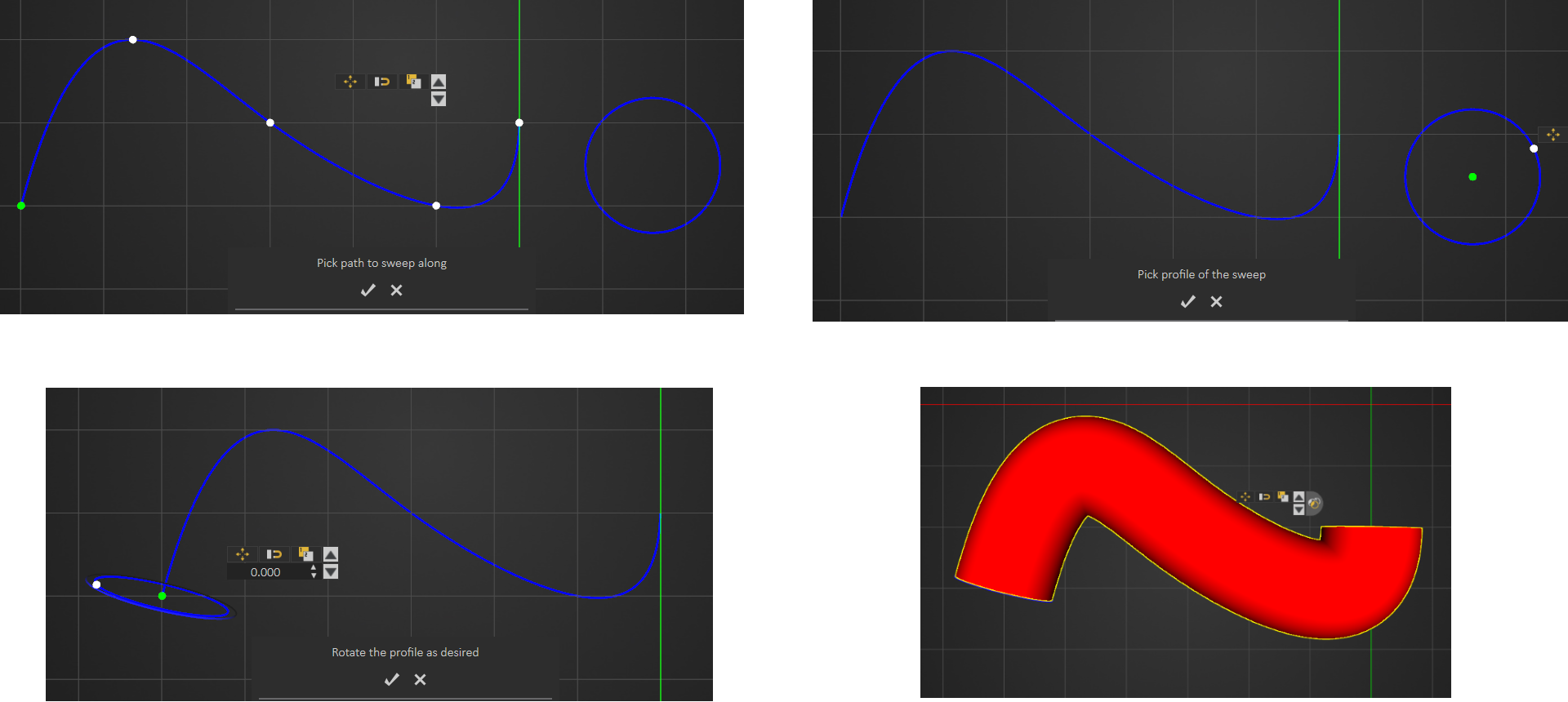
This feature enables users to extrude a shape along a created path. After creating the path and shape, select Sweep form the menu, and start by picking the path to sweep along as the message indicates. Next, select the profile to sweep, and rotate the profile as desired then click to create sweep.
Extrude
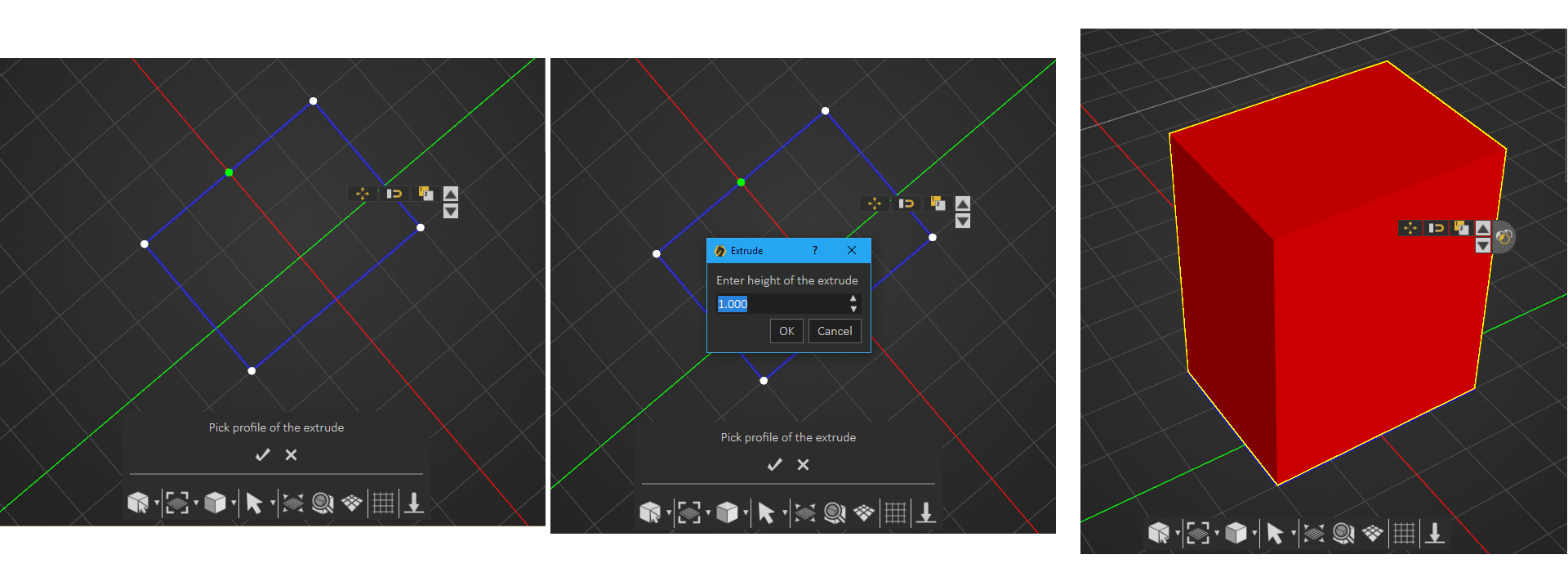
Create a closed 2D shape, then in the extrude window enter the height, and a 3D object will be created. If an open 2D shape is used the created model will be hollow.
 Wire
Wire
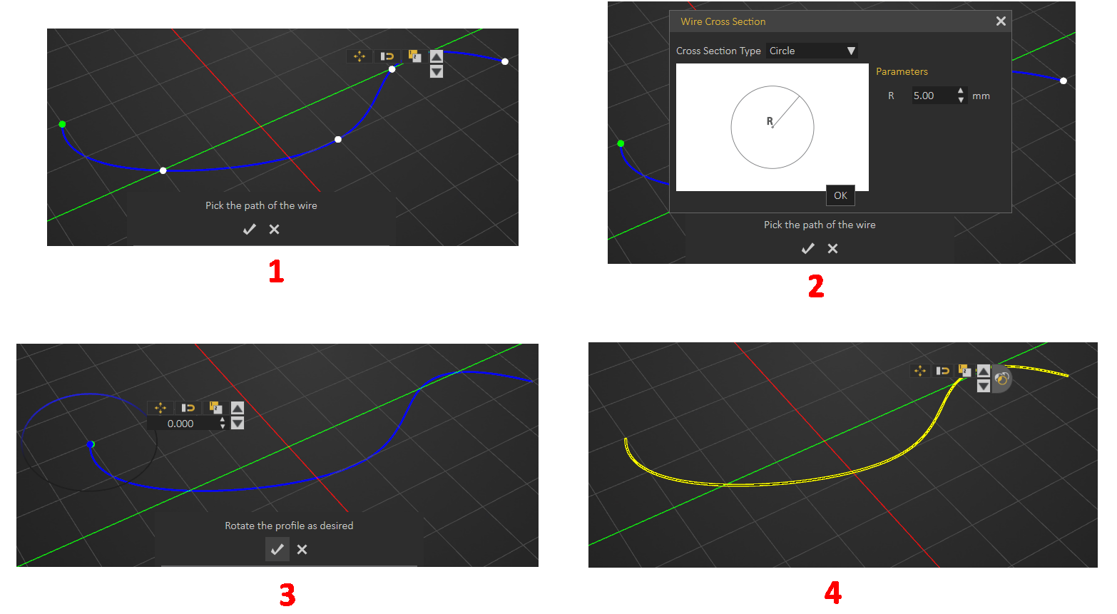
A path should be created first for the wire to follow, then the steps are as shown below. Check this tutorial on how to create wires.
Street
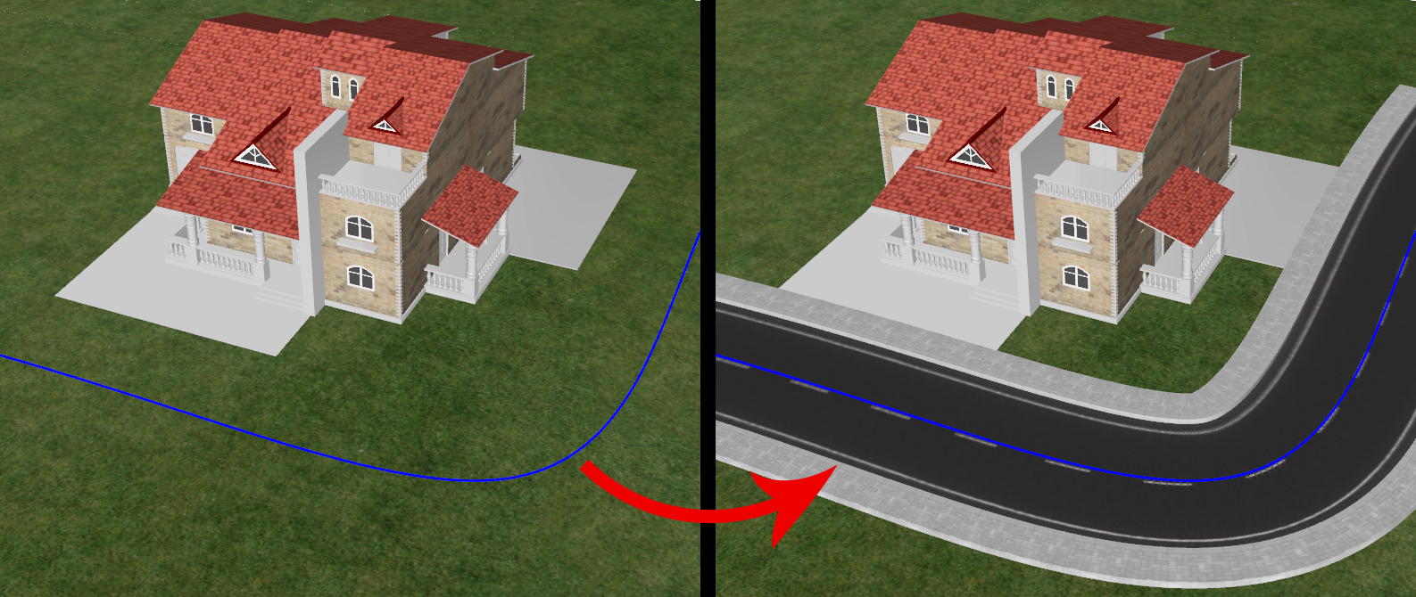
SimLab VR Studio's Street creation tool expands design capabilities effortlessly and efficiently.
- Create a path for the street to follow
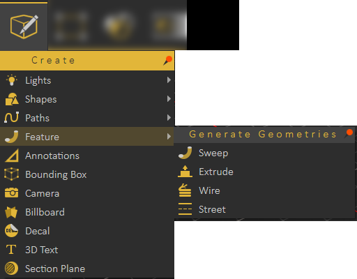
- Select the path then select Street under Features from the Create menu
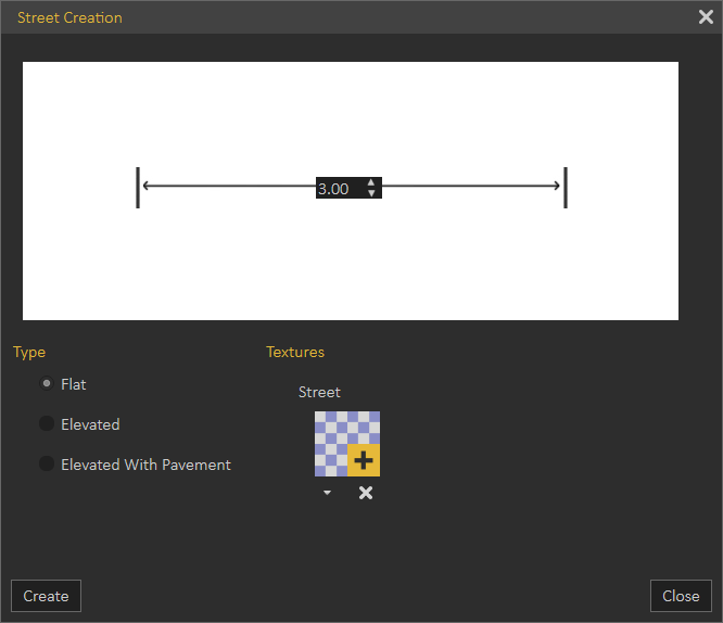
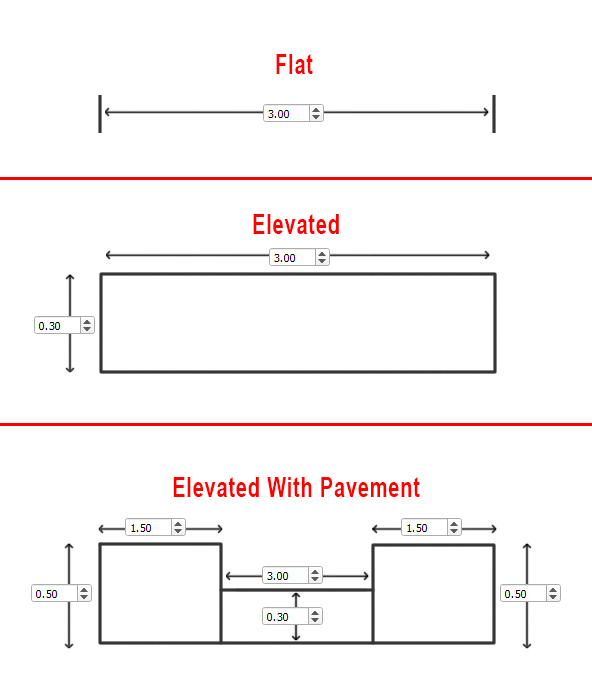
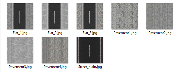
- Select the type of street from the available options
4. Select texture for street and pavement once you click on (+) in the textures side of the window.
5. Click Create and the street will appear in the 3D area and will be added to the Objects Tree
Annotations
Adding annotations and measurements to 3D scenes in SimLab VR Studio, can create a professional presentation that facilitates communicating and sharing a design.
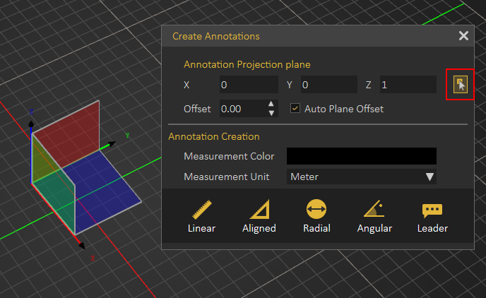
Upon selecting this option, 3D plane selection will appear to select the the plane on which to create the annotations. If it did not appear click on the Pick button highlighted in the image below.
Selecting the proper plane for the annotations creation is crucial in terms of where the annotations will be projected for viewing. You also have the option to offset the plane you have selected parallel to its axes. Measurement units can be changed in the dialog below.
Several types of annotations can be created.
- Linear, measures the projected width between two points and not the distance between them.
- Aligned, measures the distance between two points in space without projecting their location on a principal axes
- Radial, measures radial distance of 3D object.
- Angular, measures the angle between two intersecting lines.
- Leader, adds custom text with a pointer to the design.
Bounding Box Group
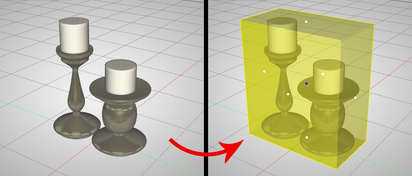
Creates a ghost box for a single selected object or a group of objects. The ghost box can then be used in a Boolean operation to modify the geometry of objects. Select an object or group of objects, then click select Bounding Box form the Create menu. The Bounding Box will appear and will be added to the Objects Tree.
Camera
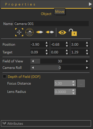
Creates a camera in the 3D area and adds it to the Scene Browser. All necessary functions for creating, and setting the different cameras can be found in the Properties dialog when the camera is selected.
Billboard
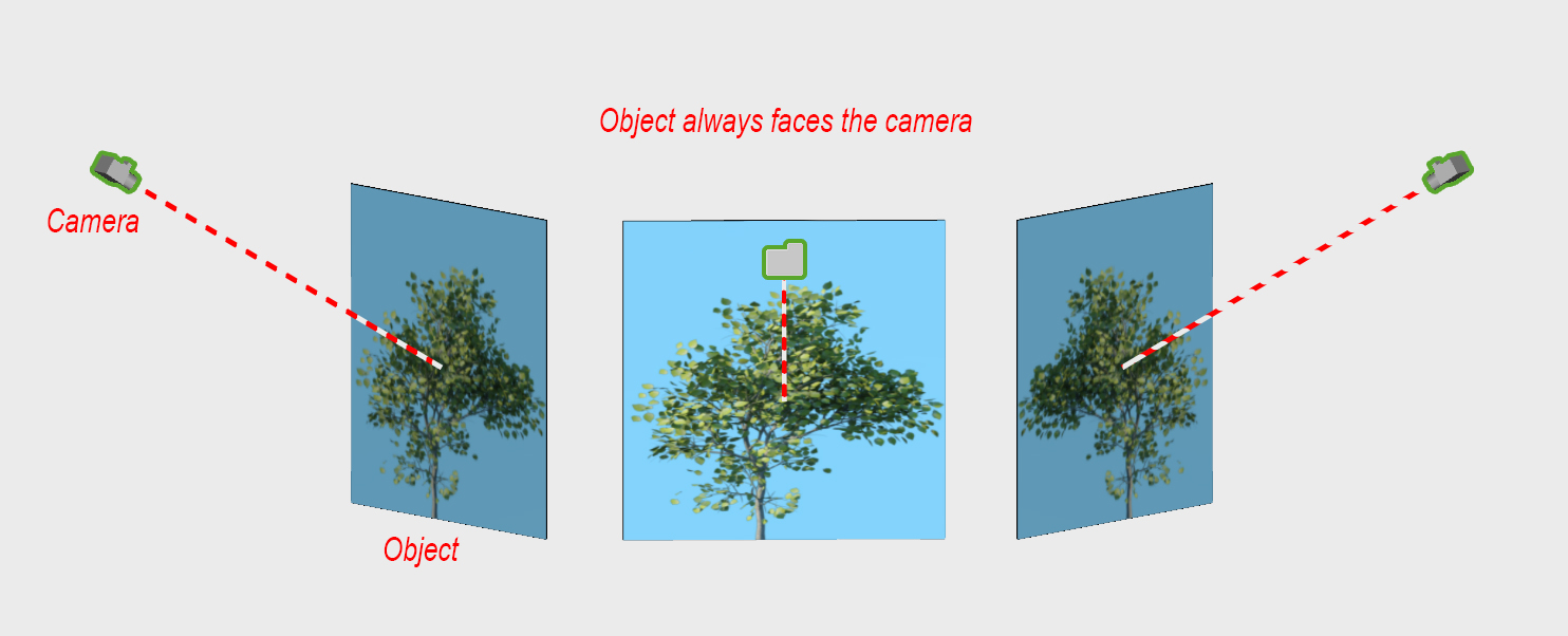
Creates geometry that will be always aligned to the current camera. The plane geometry linked to the Billboard will rotate around the local Z axis to face the viewer at all times.
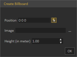
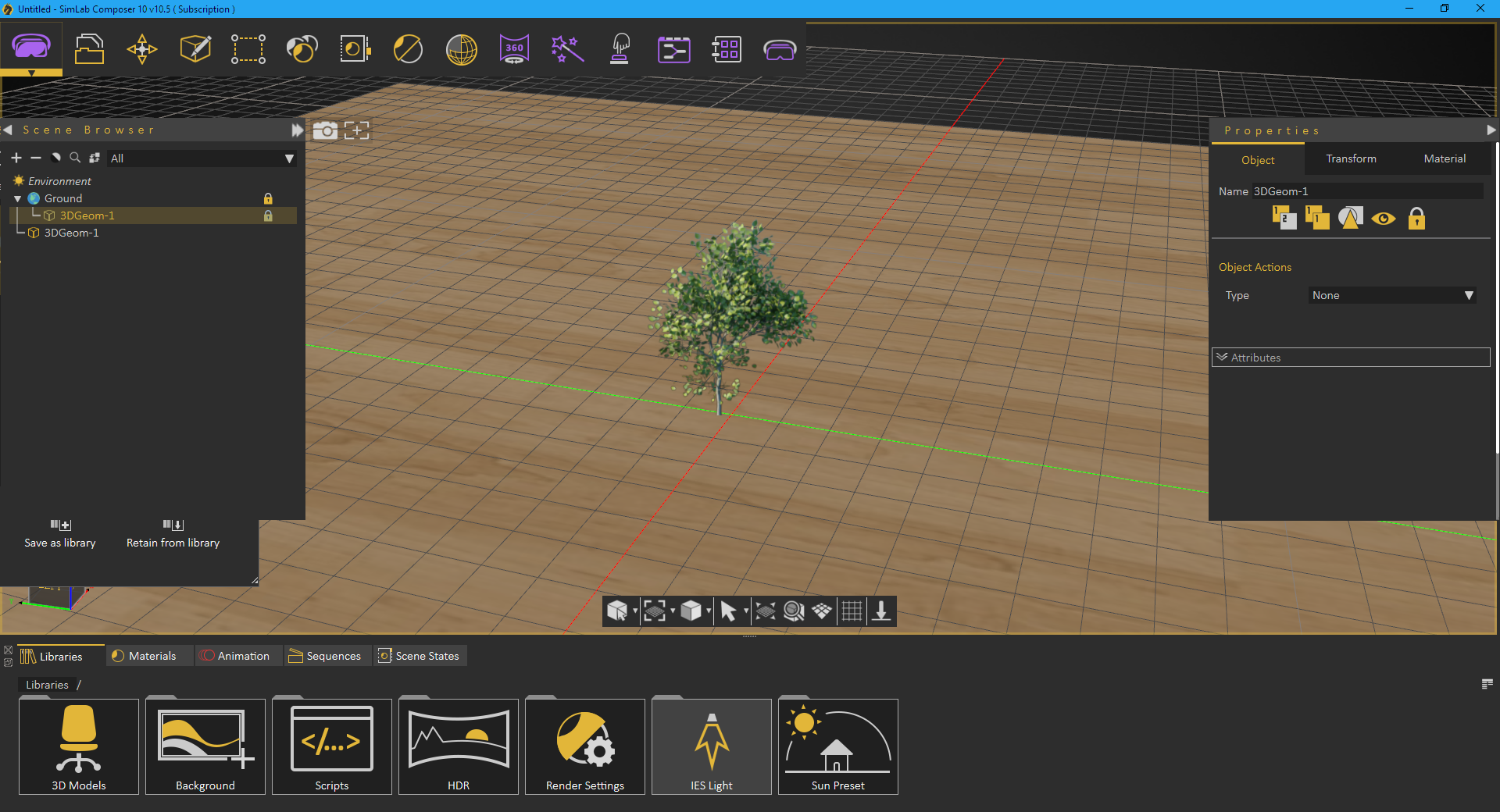
To create a Billboard, select Billboard from the Create menu, click anywhere in the 3D area to pick a position (X, Y, Z) to place the billboard at. Browse and select an image (choose PNG image format to preserve transparency). The default image will be a tree if the user didn't select an image. Enter the suitable height in meters, it takes the aspect ratio of the selected image, the width of the Billboard will be approximated automatically.
The billboard object always faces the camera, to allow architects to add PNG trees and humans to the scene.
Decal
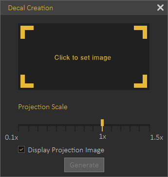
Applying a company logo, or product images to 3D models is made easier with Decal Creation from the Create menu. The parameters in the Decal window are:
- Image: Requires setting a valid path for a valid image file.
- Projection Scale: Uniform scale value applied to the decal image.
- Display Projection Image: Check box which if checked will display selected image for easier application.
To learn more about decal creation, check this tutorial, and this article
Text
2D Text
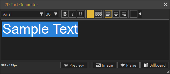
Used to create 2D text, that can be formatted as in any other text editor, as shown in the dialog below. This 2D text can be saved as a *.png Image that can be used to create Decal.
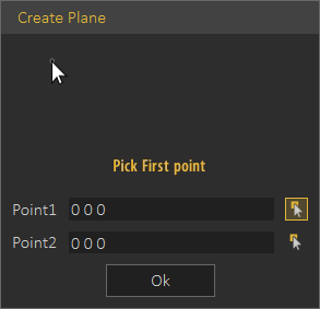
A plane can be created by picking two points, in the dialog below, and the 2D text will be attached to it.
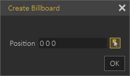
Finally the 2D text can be added as a Billboard by selecting a position for it in the dialog shown below.
3D Text
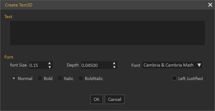
In the Create Text3D dialog, the user can type in text, and select its format. Clicking OK will create 3D text parallel to the ground at the center of the 3D area. An assembly with geometry for all letters in the text will be added to the Scene Browser, and different transforms can be applied to the 3D text. A user can also change the material of the generated 3D Text, by dragging material form the materials library, and dropping it on its geometry in the Scene Browser.
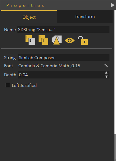
To modify anything in the created 3D text, select the text in the 3D area, or from the Scene Browser, to display its properties in the Properties Panel.
Section Plane
Section plane will be created and selected in the 3D area with the 3D dragger to enable the user to transform/rotate the section plane. Section plane effects are exported to file formats such as OBJ.
By default a section plane cuts through the whole scene. Using the Break By Section Plane tool in the Geometry menu, the user can select the geometry to cut using the section plane(s).
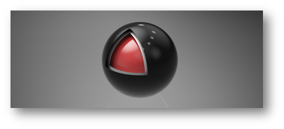
In the image shown below a scene with three spheres inside each other and three section planes were created with different orientations. Select each section plane and use it to cut through the outside and the middle spheres. To do that go to Geometry menu and with the sphere to cut being selected, select Break by Section Plane function. This will break the geometry into two in the Scene Browser and the 3D area.
Repeating this for all three section planes will split each sphere into eight parts. Deleting/ hiding some of the parts will result in the shown image.



No Comments