
Interactions Menu
Allows users to define interactions in VR scenes.
Grabbing Group
Make Grabbable
Makes selected object(s) grabbable in the scene. A grabbable object is an object that can be grabbed by a controller in a VR Experience or using the desktop hand and can be moved from one place to another.
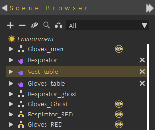
Grabbable objects are highlighted clearly in the Scene Browser
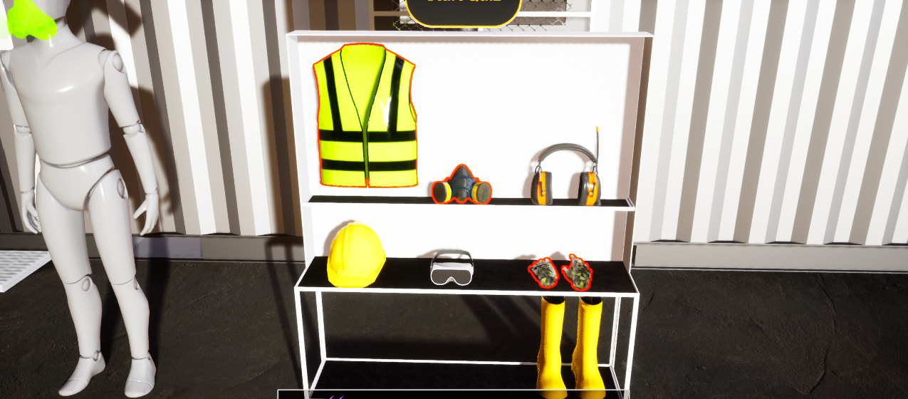
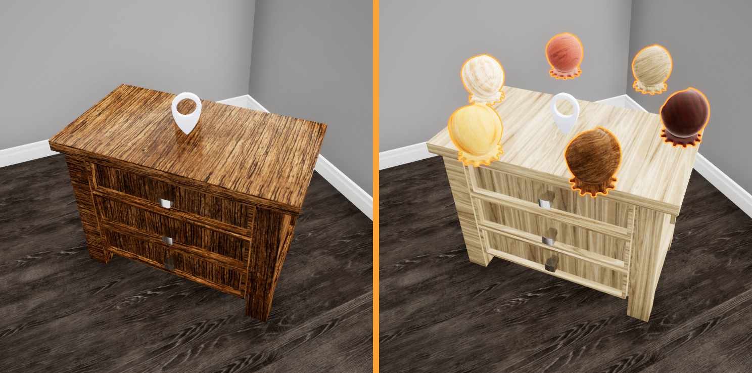
Grabbable objects are highlighted in the Desktop or VR viewing modes with orange or red highlight , as shown in the following image:
Make Grabbable Sequence
Grabbable sequences allow users to interact with 3D object(s) in the Viewer by linking them to animation sequences. In the image below, an animation to control the arm was saved as a sequence, then linked to the arm object using Grabbable Sequence. When the arm is grabbed in the Viewer the path appears and the user can move the grabbed object along the path.
The following tutorial shows how to create and use Grabbable Sequence
Dynamics Group
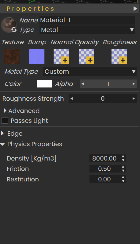
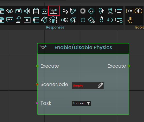
Enable Physics
The physics feature allows for the object to have physical properties such as gravity, mass and friction. To add physics to an object select Enable Physics then select the object you want.
Make Climbable
With this feature, selected objects in the scene can be made climbable such as ladders. Just click Make Climbable and select the object you want.
Check this tutorial for more about these two features.
Clipping Planes
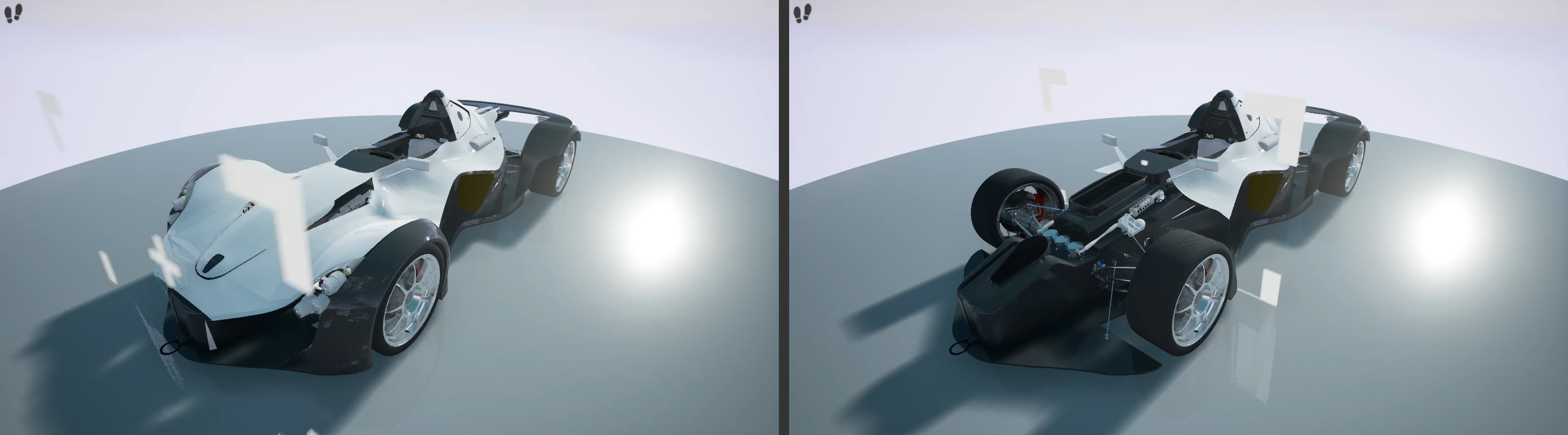
Also known as Section Planes in VR, it can be static, animated, grabbable, and turned on/off dynamically. By determining the Clipping Plane and Clippable Objects the user can make clipping effects for some or all objects in the scene. The clipping plane can be static or it can be animated showing Clippable Objects as it moves, the Clipping Planes tutorial will show you how to use Clipping Planes and assign Clippable Objects
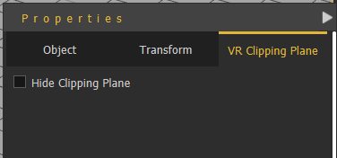
From VR Clipping Plane tab in the Properties Panel, the user can select to show or hide the clipping plane. The direction of the clipping plane normal determines the clipped section of the model.
Disassembly and Docking Group
Make Dock and Target
Dock is the static object, and Target is the (grabbable) moving one, so Target needs to be made Grababble first. After selecting this function the user will be asked to Select Dock Node, then to Select Target Node, and last to configure object orientation.
In the VR Experience, the user grabs the Target and when it is released (grab ends) while it is intersecting with the Dock, it is moved to the docking target's predefined position.
Remove Dock and Target
Selecting this function will prompt the user to Select Dock Node, and Select Target Node then the relation will be removed
The following tutorial shows how to create Dock and Target interaction in SimLab Composer and Studio:
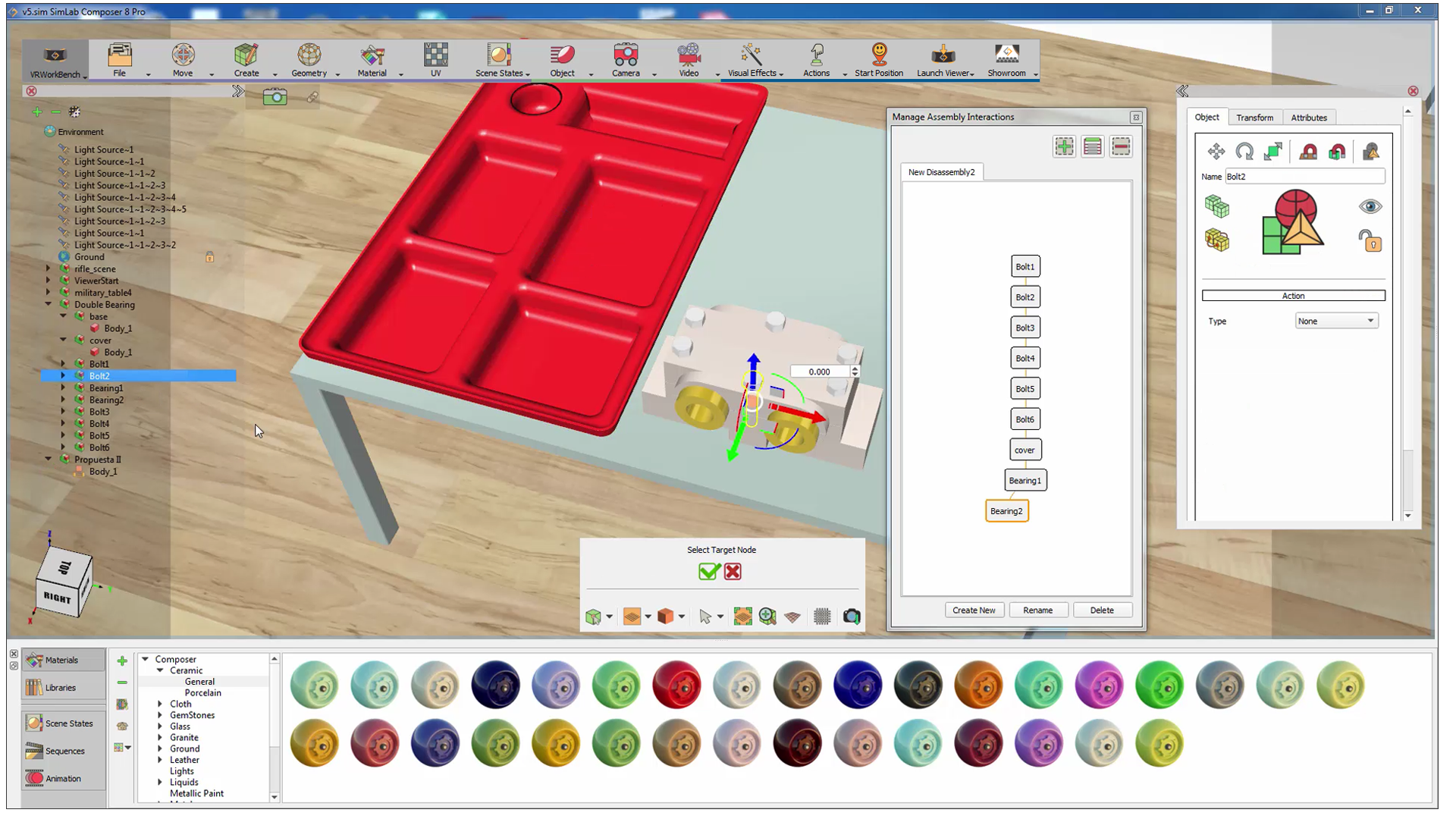
Manage (Dis)Assembly Process
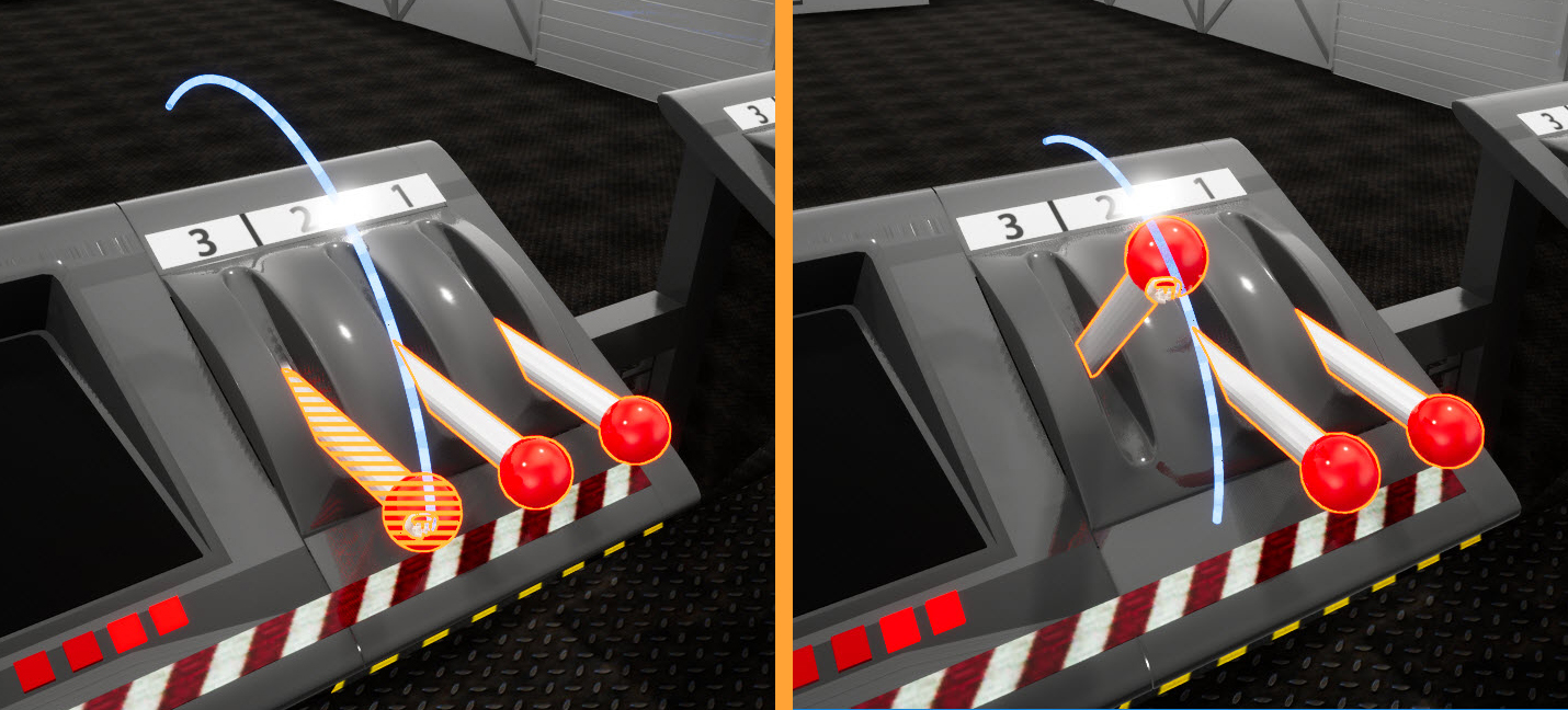
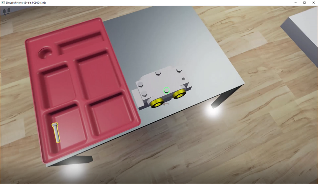
In case the assembly/disassembly process is linear, which means it goes in a defined order this function can be used. It simplifies the process and makes it move in a very specific scenario. Highlights will guide the user throughout the assembly/disassembly process with ease and without any confusion. Green highlight object in an assembly refers to the currently available part of the system that can be removed. Yellow highlight indicates that the object can be grabbed.
|
|
|

|
|
|
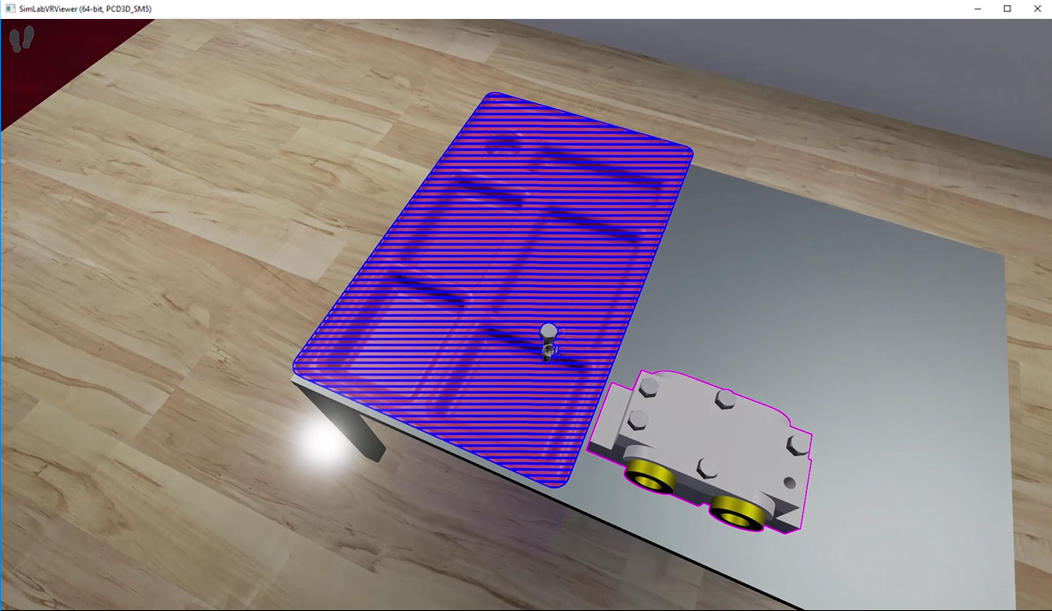
Blue highlight in the assembly indicates that the object can be placed there.
Press Right Mouse to toggle the hand. The hand has a fixed position in the view, and will teleport to the grabbable object when you click on it, and will keep grabbing as long as you hold the button.
The assembly management interactions, and settings:
Note: Training Builder can be used for creating a more open assembly/disassembly process. It can be used to define the logic for the processes, giving the user more control without forcing her/him to adjust the model structure in Scene Browser or go through a single path of exclusion.
VR Assembly System
The new Assembly/Disassembly System released in V14 of SimLab Composer and Studio (Ultimate)
Key Features of the New System: Comprehensive Assembly/Disassembly Support. Seamlessly assemble and disassemble components with precision and flexibility.
Logical Order Enforcement: The system ensures a logical process, such as requiring screws to be removed before detaching the parts they secure. However, the sequence of removing screws is flexible, take them out in any order you prefer!
Interchangeable Parts Recognition: Recognizes parts like washers and screws as interchangeable, allowing substitutions as needed.
Tool Integration: Supports the use of tools to remove or place objects, making the process more realistic and efficient.
Optional Ghost Guides Enable ghosted visuals to easily identify the correct placement for objects, simplifying the assembly process.
This system is robust enough to handle even large and complex assemblies, as demonstrated in the video below.
Industries Solutions
SimLab Studio is continuously adding new features to make the experience of its users more joyful, and easier.
Door/Cabinet Animation
Automatically creates an animation for an object depending on its type. This can be useful for scenes with multiple objects of the same type. There are two main methods for defining which objects to animate:
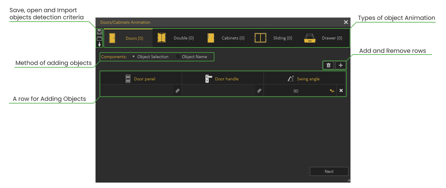
Object Selection
With this method, the user will manually select the components in the scene to create an animation for.
This method is suitable for scenes with a small number of objects. Check the following tutorial on automatic animation for Doors/ Cabinets using the Object Selection Method
Object Name
With this method, the user will type in the name of the components, and the software will automatically find them in the scene and list them.
This method is more suitable for scenes with a large number of objects to animate. Check this tutorial on automatic animation for Doors/ Cabinets using the Object Name Method
Doors and Cabinets Settings
- Send animation to timeline: Enabling this option sends the created animation as keyframes to the Animation Timeline. This can be helpful when you intend to combine multiple animations or modify the animation further.
- Create animation Sequences: This option creates separate animation sequences for each object, those sequences can then be used in VR.
- Animation sequence naming convention: The user can select the naming method for the sequence.
- Attach sequences: This makes the scene ready to be used in a VR Experience. Sequences can be applied as Actions (executed when the user clicks on a door or panel) or as Grabbable Sequences (the user can open or close interactively in the VR Viewer)
- Create reversed versions: Reversed version of animation allows the object to go back to its original state. For example, if you have created an animation for a door opening, a reversed version of the door closing will be automatically created.

Visualize Scene Options
Visualize scene options (scene states and animation sequences) by displaying them as entities in a 3D world for easier and more practical VR Experiences. Check this tutorial on how to visualize scene options in VR.
Press "3" on your keyboard in the VR Viewer to show available Pins, "LBUTTON" to select Scene States/Animation Sequences that appear as entities from the Pins.
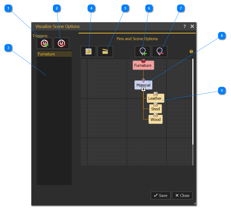
| 1 | Select a Scene Node from the Objects Tree or from the 3D area, then click this option to add a Pin to the selected node, showing its scene states if interacted by the user in SimLab VR Viewer. |
| 2 | Remove a Trigger and eliminate any associated Pins and scene options. |
| 3 | The list of Triggers. |
| 4 | Activates Scene States library to drag-and-drop Scene States from it into Pin nodes. |
| 5 | Activates Animation Sequences library to drag-and-drop Animation Sequences from it into Pin nodes. |
| 6 | Add a new Pin to the selected node to hold other scene options chosen by the user. Once added, either Scene States or Animation Sequences from their corresponding libraries can be dragged and dropped into it. |
| 7 | Remove the selected Pin node from its diagram. |
| 8 | Scene States/Animation Sequences can be dragged-and-dropped here from their corresponding libraries. |
| 9 | Added Scene States/Animation Sequences |
Visualize Scene Options - Step by step
- Create multiple Scene States/Animation sequences (at least two), for a 3D model.
- From the Interactions menu click Visualize Scene Options.
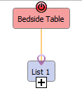
- Select the object for which to make a list, Ex: Bedside Table, select the table model then Add a Trigger by clicking

- The object name (Bedside Table) should appear on the Pin and Scene Options side as shown in the image.

- Drag and drop created Scene States/Animation Sequence (created in step one) from their libraries into VR List1 one by one
- The Scene States/Animation Sequence will appear under the VR List1
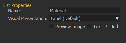
- Select List 1 to display its properties, and change its name, and properties


Snap and Socket
VR Snapping feature makes building scenes in VR easier and more intuitive. Whether you're designing a kitchen or creating an educational lab, VR Snapping allows you to effortlessly add items and align them perfectly without any extra effort. Setting up VR Snapping in Composer/ Studio is simple and gives you full control over how it behaves in the VR environment. Watch the video below to learn how to use VR Snapping
XR Anchors
When viewing scenes in XR mode on your Quest headset, you'll be able to attach 3D models to specific physical locations in the real world.
This feature enables you to:
Place training models in actual examination rooms.
Add visual highlights to real-world objects.
Visualize furniture placement in your space.
Watch the tutorial below to see XR Anchors in action.
User Gadgets Group
Add User Gadgets
This function will add some gadgets to the Viewer start model, as shown in the dialog below:

Adjacent Objects: These are objects that move with the Viewer start model in the VR environment. They can be something like tools (screwdriver or hammer). Check this part of the tutorial for more about Adjacent Objects.
Controllers: This allows the user to change the VR controllers with selected 3D models for hands, or gloves. Controllers appearance is only available in VR Mode. The following video shows the effect of using Controllers in the VR experience.
The following tutorial shows how to use controllers gadget in SimLab Composer/ Studio.
Hud: Hud is a plane shown in front of the user so it is easy to show instructions or current status. The following video shows the Hud appearance in a VR Experience.
The following tutorial describes how to add/use Hud and Adjacent Objects
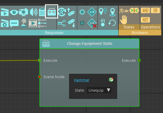
Change Equipment State response in the Training Builder, which can be used to control equipment state (Equipped or Unequipped) for all gadgets (Adjacent Objects, Controllers, and Hud)
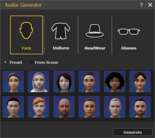
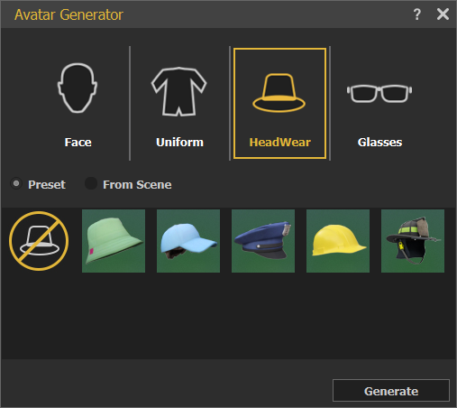
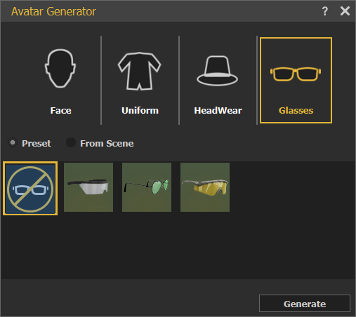
Avatar Generator
In this dialog users can build their own avatars from a collection of Faces, Uniforms, Headwear, and Glasses. Avatars are used in VR Collaboration, in SimLab VR Viewer. For more about Avatar Types and Creation check this tutorial

Voice Commands
AI Agents
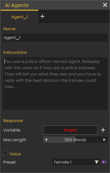
With this feature To learn more about this feature check the following tutorial.
No Comments