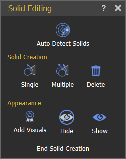
Solids Menu
To create a simulation the first step is to convert the 3D design to solid parts that can be physically simulated. This can be done either manually by selecting the parts and converting them to solids, or by clicking on Auto Detect Solids which will automatically detect the objects in the scene and convert them to solids.
- Auto Detect Solids
- Solid Creation
- Appearance
The Geometries Tree and the Models Library are associated with the Solids Tab. Once the Solids Tab is activated, they will be displayed on the left side and bottom of the application window, respectively.
Auto Detect Solids
Automatically identify and classify a model's geometries and assemblies into solids, by running an algorithm, where each solid contains either one geometry/assembly or a group of geometries/assemblies.
In the image below, the simulation workspace with an imported model is shown. Solids in the model has been detected and shown in the Solids Tree.

If the imported model is from an analytical file format like STEP, this algorithm makes use of the solids hints already embedded in an object to identify it as a solid.
In some cases, the automatic detection method may not yield the required results, the manual method for creating solids gives the user more control over solid creation.
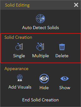
Solid Creation
Sometimes more control over solids creation may be needed. So rather than using the automatic detect function, Solid Creation section functions in the Solid Editing dialog are needed.
- Single: Manually creates a solid from the selected geometries or assemblies, geometry or an assembly can be selected either using the Geometries Tree or from the 3D Area. Multiple geometries can be selected from the Geometry Tree by holding the Ctrl key on the keyboard and clicking the desired geometries, then pressing the Create Solid button in order to create the desired solid. After clicking the Single button, only one solid will be created and all of its corresponding geometries will disappear from the Geometry Tree and move to the Solids Tree.
- Multiple: Manually create solids from selected geometries or assemblies. After clicking the Multiple buttons, multiple solids will be created and all of the corresponding geometries will disappear from the Geometry Tree and move to the Solids Tree.

Appearance
Sometimes, you may want a certain object to inherit the movement of a specified solid without including it in the equations of motion used by the corresponding solver, here the Manipulation Toolbar comes in handy. You find only one button in the Manipulation Toolbar, as shown in the following image:
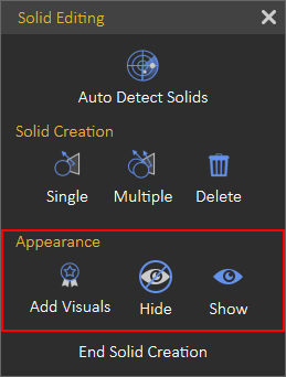
Add Visuals
Attaches selected geometry to an existing solid as a visualization object for visualization purposes that are not included in the simulation calculations. To add visuals, select the desired object(s) from the Geometry Tree, then click the Add Visuals button. Once it is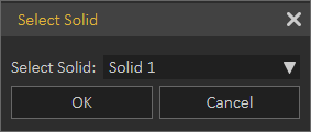 clicked, the Select Solid dialog box appears for the user to select the desired solid to attach visuals.
A solver is a component in SimLab Composer. SimLab Composer provides a library of solvers, each of which determines the time of the next simulation step and applies a numerical method to solve the set of equations that represent the model.
The Visual Icon appears next to the visual object's name in the Solids Tree. You can toggle this icon to turn it back as a normal object combined with the solid.
Visual elements can be disabled or enabled in the Solids Tree only if the Solids Tab is activated.
Hide / Show
This tool makes work easier while creating solids in complex models. It is considered a handy tool while working in simulation, where the user can hide/show objects in the 3D area.