Main Toolbar
- Main Toolbar
- File Menu
- Move Menu
- Create Menu
- Geometry Menu
- Material Menu
- Scene States Menu
- Render Menu
- Baking Menu
- Help Menu
Main Toolbar
The main toolbar in SimLab Composer is located at the top of the application giving the user access to the different menus, this is the main toolbar for the VR workbench:

File Menu
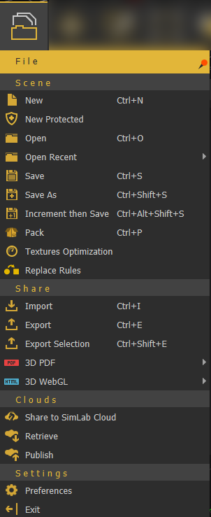
Scene Group
New/New Protected
Clears the current scene, then displays Welcome (new scene dialog), where the user can select to open a ready-to-use environment, open a scene, or create an empty one.
Images for the last opened scenes are displayed under the Recent Files tab for quick access.

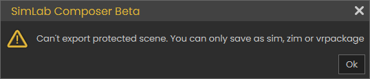
New Protected option is the same as creating a new scene, except that this scene can only be saved as sim, zim, or Vrpackage. If the user attempts to export it into any of the available formats, the below message will appear. This is done to protect users' property 3D models from being used by others.
Open/Open Recent
Open will open "Open Composer file" dialog, where the user can browse to a *.sim or *.zim file to open. The Open Recent on the other hand will show a list of the last few *.sim or *.zim files that were opened.
Save/Save As
Opens Save Composer file dialog, where the user can select the name and location for the created *.sim or*.zim file format
Note: Sim file (*.sim) is the native file format for Composer/Studio. It stores the scene, but it does not include contents it references in the disk space. For moving files between machines it is better to save the scene as Zipped Sim File (*.zim), which collects all needed resources (textures, sounds, thumbnails, and other resources) and saves them in a single file that can be passed between machines as it is contains all what is needed.
Sim and Zim files are compatible between SimLab VR Studio and SimLab Composer in case you need to open a file for rendering, or using any other feature from SimLab Composer. Models can be moved in (*.zim) format and both VR Studio and SimLab Composer should be of the same version.
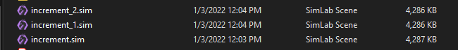
Increment then Save
This feature (with shortcut Ctrl+Alt+Shift+S) will save new increments for the same (*.sim) file. These increment files can be helpful in undoing a feature in a complicated scene after some time. So the user can go back to the file before the feature was added and continue from there, in other words, creating lots of backup saves in case something wrong happens.
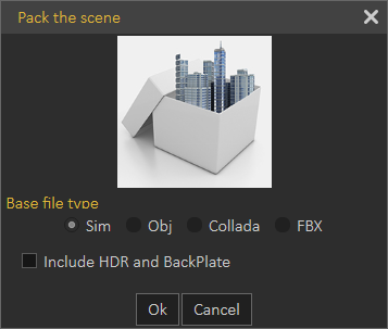
Pack
In addition to *.zim you can use pack the scene to pack the model and its textures in one zip file. Supported formats to be used for Packing include OBJ, Collada, and FBX. This is used usually to move files to other applications on other machines.
Scene Optimization
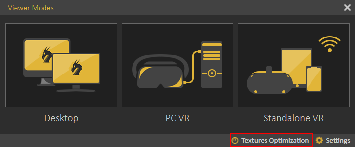
In VR and especially when using stand-alone devices like Quest, Pico, Android, or iOS, it is important to make sure you are not consuming a large amount of memory for textures on those devices to have a smooth VR Experience.
This option contains option for the optimization on 3D objects, texture or lights objects in the scene all in one dialog, the following video will explain the content of this dialog:
The dialog can also be accessed from Show in Viewer dialog, under the VR Viewer menu.
Replace Rules
Replace rules makes it easy to replace geometries in the imported file with new entities. For example you can replace a simple cube geometry named "fire" with VR Fire effect. It also supports replacing material types, for example each material that includes plastic in its name can be automatically converted to a plastic material.
This tool is usually used by 3D designers, where they do not need to repeat tasks in SimLab Composer when moving their models.

Share Group
Import/Export
Opens the corresponding Import/Export Geometry dialog. The import function enables the user to build scenes of 3D models from different file formats. The export function, on the other hand, enables the user to share the created 3D scenes with others in different file formats.
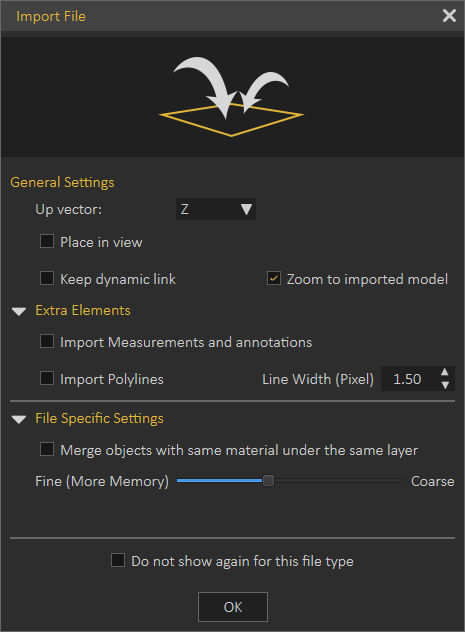
In the Import Geometry dialog, the user can browse to 3D geometry to import. Clicking Open displays the Import File dialog, where the user can set different options for 3D import. General Settings include Up vector, Z axis is selected by default. The user can choose a different axis depending on the design of the imported 3D geometry.
Place in view, places the import geometry in the current view, rather than the center of the scene. Keep dynamic link, when checked keeps 3D geometry linked and automatically updates to any changes in the home CAD application.
Zoom to imported model, imports the object to the center of the scene and zooms the camera to it.
Import Measurement and annotations, will import these elements with the 3D geometry.
The Import File dialog will have more elements depending on the imported file format. The image on the left below, is for 3D PDF file import, while the one on the right is for DWG file import.
|
|
 |

Export function will open the Export Geometry dialog, and will enable the user to export the 3D model to any of the supported file formats. For a list of supported Import/Export file formats, visit this page.
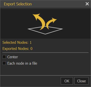
Export Selection
The user can select specific nodes/objects from the scene to be exported. The objects will be exported to the specified folder with their names in the Objects Tree.
 |
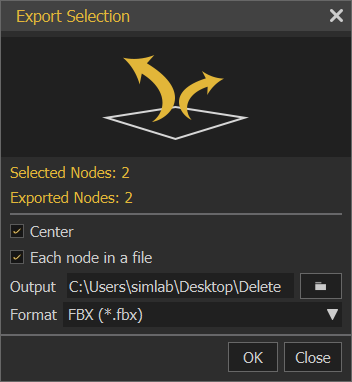 |
Export Selection can be used to export a single part from the 3D scene or to create a VR Catalog, from the exported selections *.vrpackage(s). Creating VR Catalogs is a feature in SimLab Composer Ultimate edition. The following video shows export selection in action:
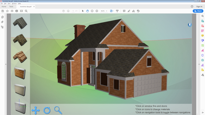
3D PDF
3D Scenes created in SimLab Composer can be exported into custom-designed 3D PDF files, using SimLab Template Designer. The exported 3D PDF files can be opened using the free Acrobat reader (version 9.0 or newer), to take advantage of all the features in the generated 3D PDF file.
Features exported to 3D PDF files, as well as to HTML/WebGL files are listed in the table below.
|
Exported Features
|
3D PDF Files
|
HTML5/WebGL Files
|
|
3D models and Geometry
|
√ | √ |
| Textures | √ | √ |
|
Materials and Colors
|
√ | √ |
|
Scene States
|
√ | √ |
| Visualized Scene Options (Lists) | √ | √ |
|
Animations
|
√ | √ |
|
SimLab Actions
|
√ | √ |
|
2D Polylines and Annotations
|
√ | |
|
Cameras
|
√ | √ |
|
Reflection Maps
|
√ | √ |
|
Bump Maps
|
√ | √ |
|
Custom Designed Templates
|
√ | √ |
Before attempting to export to 3D PDF, the user needs to choose 3D PDF Settings and make sure to include 3D Area in the template.
Tutorial video showing how to export 3D models to 3D PDF and visualize it with others using the free Acrobat Reader.
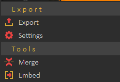
3D WebGL
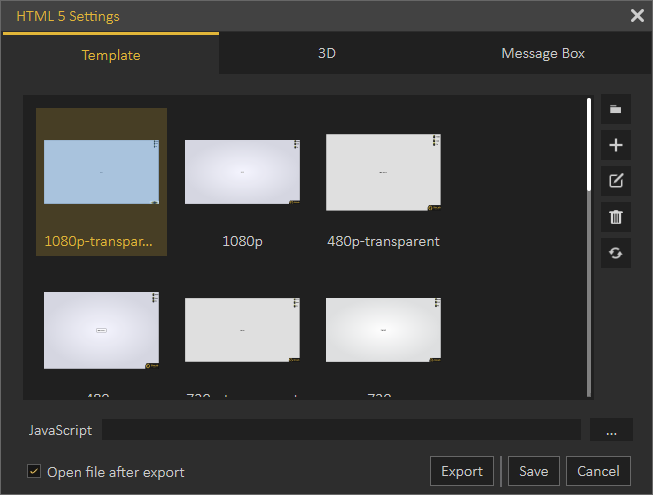
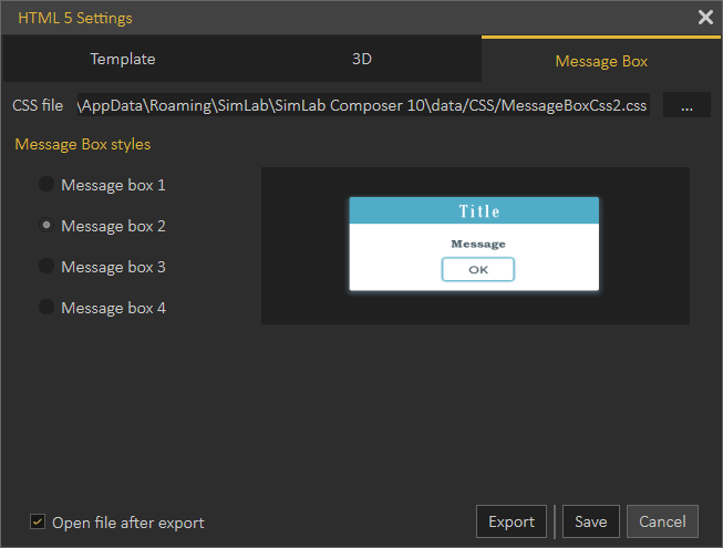
HTML5 Settings dialog enables the user to control the generated HTML file(s). Before exporting to HTML, the user needs to select a template to use for export and to set other HTML parameters.
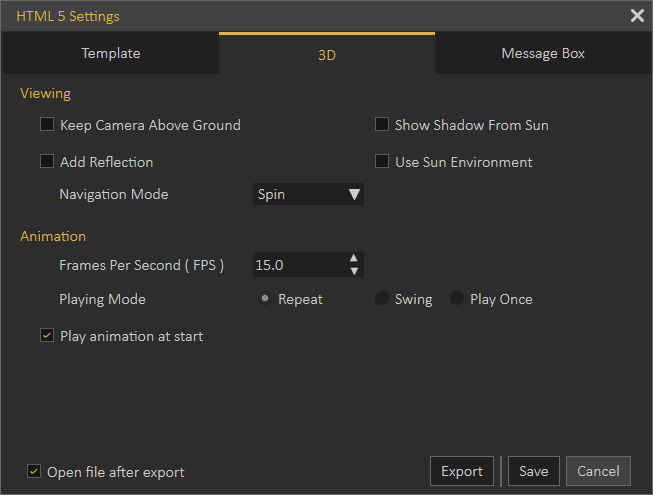
The HTML template design is fully supported with an advanced 2D layout, the same one found in the 3D PDF template designer. Behavior Actions can be exported into HTML5/Web GL, enabling users to create an interactive 3D experience on the web. Reflection maps, sunlight, and shadows are applied to 3D models and exported to HTML, giving them a more realistic look with smoother camera navigation and better material appearance. 3D scenes can be exported into HTML5 files, the same way 3D PDF files are exported.
From 3D WebGL under the File menu, click Settings to open the HTML5 Settings dialog, where the user can select the template to use from the Template tab. The template tab is where the user can browse the folder containing the HTML template(s) to use, and create new templates, edit, delete, or refresh template(s).
Clicking the New button will open the SimLab Designer window. SimLab Designer is a simple application that enables users to design and save their own templates. Page size under the File menu of the template designer can be used to expand the background image when the Web GL is set to full screen. For more details about SimLab Designer, select Designer Help from the Settings/Help bar in SimLab Composer.
Document Javascript and 3D Javascript can be added to control both, the HTML document, and the included 3D model.
Java scripts can be applied to designed templates, to make specific actions. Details about Javascript support in WebGL can be found under Help in SimLab Scripting.
With a template selected, click Export from the menu or in the HTML 5 Settings dialog, then enter the name and location of the (*.html) file and click Save. The Export File dialog will open, where general final settings can be checked. If the Open file after the export checkbox is checked then the HTML file will open.
For 3D scenes with scene states defined, the Manage Scene States dialog will appear upon clicking Save. There the user can check the scene states to include in the exported HTML file, and their order.

Clouds Group
Share to SimLab Cloud
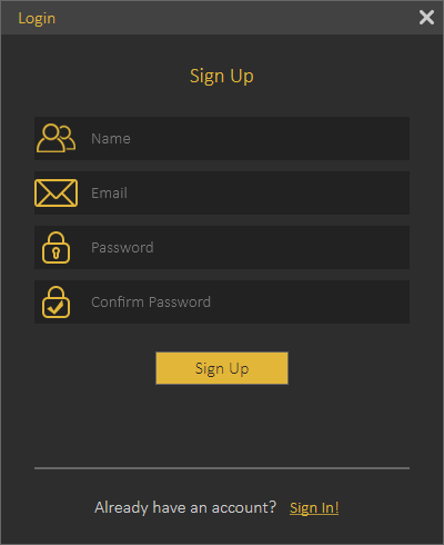
This function enables users to share their 3D scenes as VR Package on SimLab Cloud. When selecting this option the Login dialog will appear, where the user can Sign Up/Sign in.
Once the user logs in, the Cloud Sharing dialog will appear, allowing the user to share created 3D scenes with full features as VR Package. Full features mean all created animation, scene states, actions and more. By default, a user will start with a trial sharing space of 2 GB valid for 3 months.
|
|
|
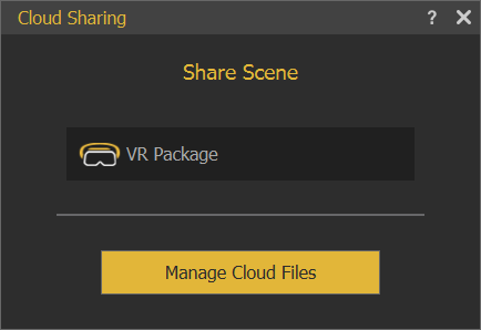

A user can manage uploaded files by clicking the Manage Cloud Files button in the Cloud Sharing dialog, which will open the Sharing Manager dialog. As the sharing period or space are expired, a user can purchase SimLab sharing keys. To learn more about sharing methods and capabilities please refer to this video tutorial (Share VR Package section ONLY).

Settings
Preferences
Common settings for 3D scenes can be adjusted once in the Preferences dialog.
Appearance Tab
In this tab the user can set the preferred appearance options in SimLab Composer, including:
Language and font: The user can select the language and the font style to be used in SimLab Composer from the supported languages combo box, and available fonts list. Changing the language, and font takes effect next time SimLab Composer runs.
Style: Change the transparency for the Objects Tree, and set appearance for 3D area. The 3D area appearance can be set as color, or background image.
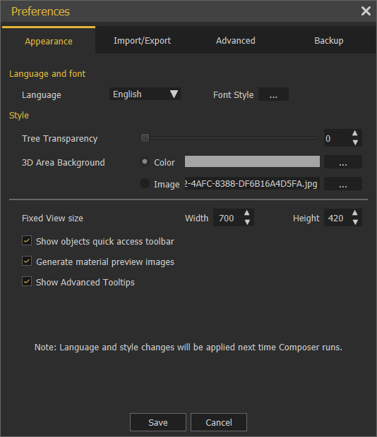
Show Objects Quick Access Toolbar: shows the Quick Access Toolbar for ease of access for its objects functionalities.
Generate material preview images: generates preview images to the scene materials in the Scene Materials dialog.
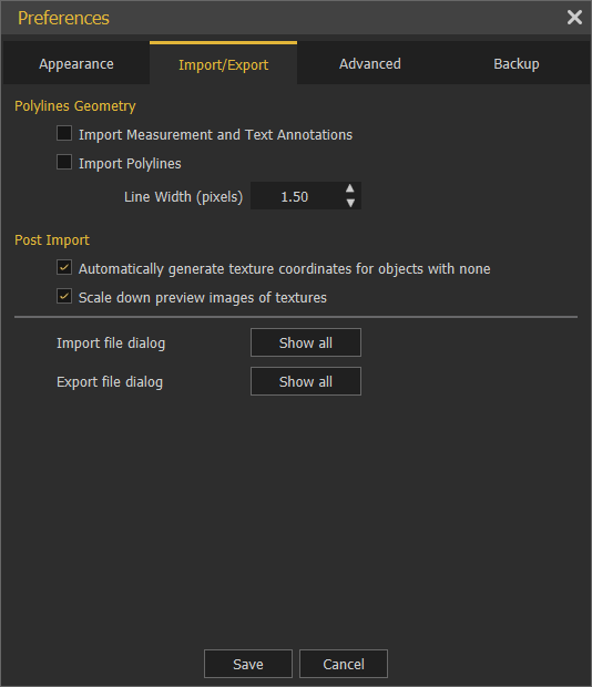
Import/Export Tab
Import measurements and text annotations: The user can select to import measurement and text annotations created in the design CAD package.
Import polylines can also be checked, and the width of the imported lines can be specified.
Automatically generate texture coordinates: Texture coordinates for the imported geometry will be automatically generated when this option is checked.
Scale down preview images of textures: Reduces the size of textures images for improving interactivity.
Import/Export File dialog is shown by default. So every time the user imports or exports models/ scenes the dialogs will appear.
If "Do not show again for this file type" option in the dialog is checked, the user can click the "Show all" option and that will reset the dialogs to show for all.

Advanced Tab

Annotation Settings group: the user can select to let SimLab Composer auto set the size of the annotations, or set its Default Size. Measurement Units, and its Precision can also be set here.
Camera Settings group: has two options Keep Above Ground; stops the camera rotation at the ground level, and will not go below, and it is applicable to Parallel and Perspective cameras.
Two Sided Lighting: when checked will draw faces twice so it is always visible, it may give better visualization, but it is recommended to uncheck this option for large scenes.
Directories Settings group: the user may select to move the User Data directory to a new location, the user should copy the original data to the new location before setting the new User Data folder.
Reset Composer data button: will reset the composer data to its original settings.
Flying Mode Settings group: it allows the user to adjust flying and rotation speed while navigation inside Composer, when using the keyboard keys for moving and mouse for looking around.
Backup Tab
Auto-Save option with its attributes is in this tab. The user can enable this option here and set its properties shown in the image below:

In the image below Enable Auto-Save is checked with a certain notification time. Action countdown until saving is the start time the countdown will appear as shown below. The notification position is set to the Right bottom corner.
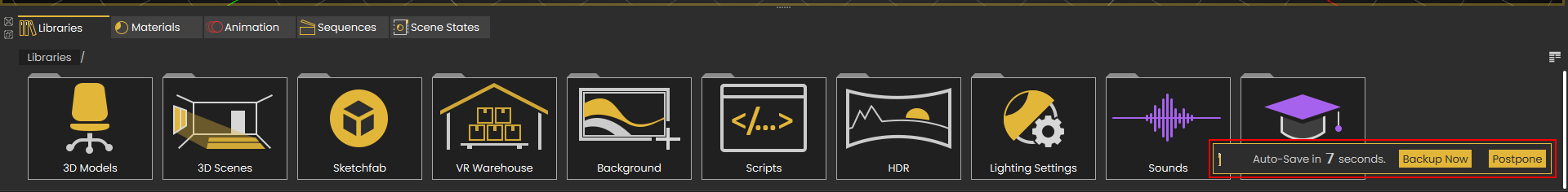
Singular and Incremental Auto-Save modes: Singular keeps only one independent auto-saved file located next to the scene file. Incremental on the other hand keeps independent auto-saved files located next to the scene file.
Exit
Will display the Save File dialog for the user to save the current scene before exiting the application.
Move Menu
Includes all Transform/Snap/Pivot Tools necessary for positioning any geometry in a 3D scene.
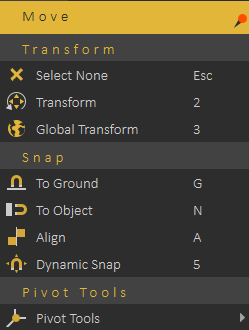
Transform
Transform functions are used for placing 3D models.
Select None: will clear selection, shortcut (Esc button)
Transform: Displays transform axes on the selected object, allowing the user to move, rotate, and scale the object. The transform axis will be aligned with the object orientation as shown in the image below. shortcut (2)

Global Transform: Displays transform axes on the selected object, allowing the user to move, rotate, and scale the object. The movement axis will be aligned with world axes, so direction is not affected with selection rotation, shortcut (3)
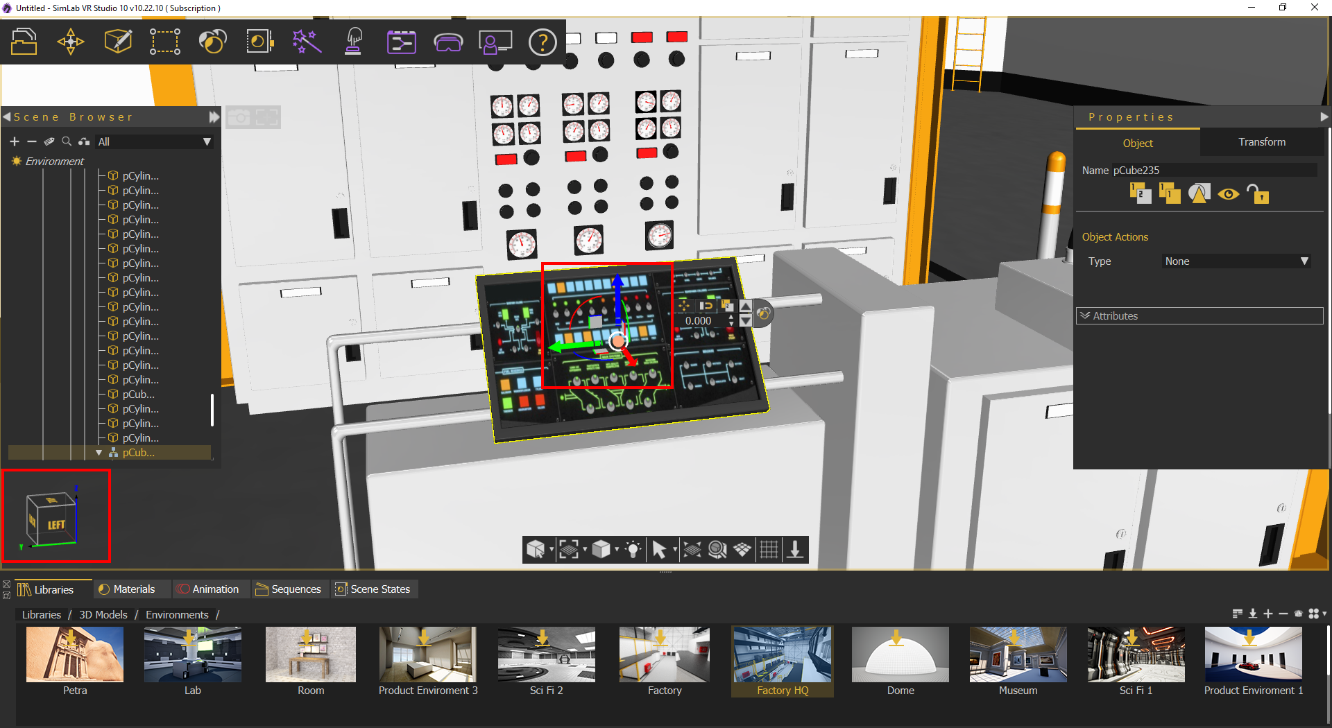
When the user clicks any dragger, a small scroll combo box will appear in the Quick Access Toolbar. The user can use this box to input exact numbers for translation/rotation/scale or can just scroll up and down. If the user prefers to freely drag the 3D geometry, this can be done using the dragger in the 3D area

Snap
Snap functions are used for aligning 3D models, and there are two types:
Snap To Ground: Snaps the selected object(s) to the ground, shortcut (G)
Snap To Object: Prompts the user to select the object to snap to, then snaps the selected object(s) to the target one, shortcut (N)
Align: Aligns selected object(s) along a user defined axis, can be used in conjunction with SimLab Composer's picking modes, shortcut (A)

Dynamic Snap: A smart tool that aids the user in placing an object in accordance with its surrounding. When activated, a blue box will envelope the selected object which in turn will snap and collide with nearby objects giving the user a guide on how to place the object without penetrating other objects in the scene, shortcut (5), check this tutorial
Pivot Tools
The pivot of a 3D geometry is the point around which transformations to that geometry are applied. By default pivot is in the center of the geometry, if you want to rotate the object around one of its sides instead of its center, you need to move the pivot.
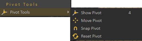
- Show Pivot: Shows pivot point for the selected geometry and grant control over its location and rotation, shortcut (4)
- Move Pivot: Allows the user to move the pivot point to another point location. The user can make use of the Pick Mode options described in the Common Toolbar, to help in selecting the point's location accurately.
- Snap Pivot: Requires the user to select two points, and the pivot of the 3D geometry will be snapped to the center between them. The user can make use of the Pick Mode options described in the Common Toolbar, to help in selecting points accurately.
- Reset Pivot: This function restores a modified pivot location to the center of the selected geometry.
Create Menu
Enables the user to create different scene elements that can add value to 3D scenes.
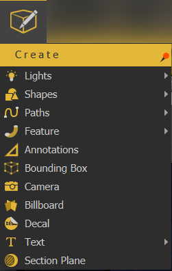
Lights
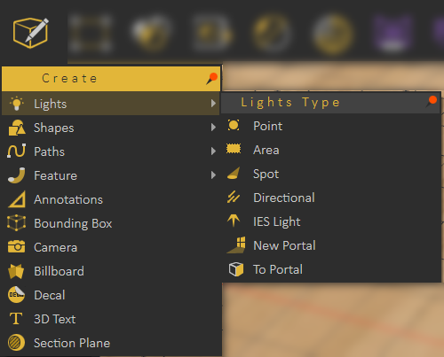
Light sources in SimLab VR Composer:
Point Light
Creates a spherical Light Source geometry and adds it to the scene. Point lights can be moved and positioned, using any of the move draggers.
The light properties can be found in the Properties Panel, to the right of the 3D area. There, the user can edit the light properties, like changing its color, or its power. The following image shows properties of the point light.

Area Light
Depending on the effect the user needs, this is another light type that can be used. Same as Point light, area lights have parameters that the user can change in the Properties Panel.
Spot Light
In addition to the main light properties, spot light has blend property that reduces the sharpness of the spot light making it blend with the environment. It also has Cone Angle property that sets the angle of the light.
Directional Light
Directional lights are for exterior scenes. The user can change the direction of the light but not its location. Other parameters for this light include, light color, light power, and light name.
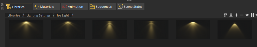
IES Light
IES Lights describe light distribution, the user can create an IES light from the Create -> Lights menu or from the Library -> Lighting Settings -> IES Light as shown in the image below
Shapes
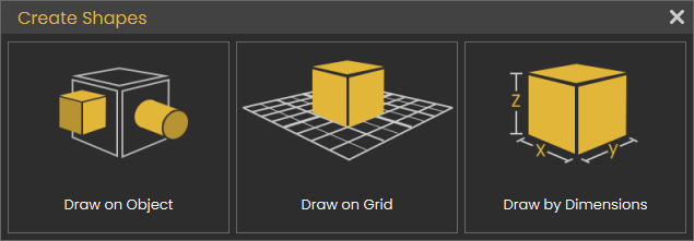
The shapes are Plane, Box, Sphere and Cylinder;
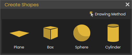
First the user needs to select the method for creating the 3D shape as follows:
Draw on Object
This way is useful when the object is rotated and an object needs to be added on it. Check this tutorial to learn more about this function.
Draw on Grid
Creates 3D shapes based on the size of the grid dimensions. Select the plane to draw the 3D shape on, then select the shape. Check this tutorial to learn more about this function.
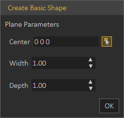
Draw by Dimensions
The user needs to input coordinates/dimensions for the shape to draw in the Create Basic Shape dialog as shown below:
Plane: Creates a 2D Plane, in Center field, coordinates are entered. Width and Depth values determine the size of the created plane.
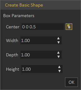
Box: Creates a 3D Box, in Center field, coordinates are entered. Width, Depth, and Height determine the size of the created box.
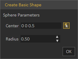
Sphere: Creates a 3D sphere, in Center field, coordinates are entered. Radius determines the size of the created sphere.
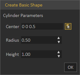
Cylinder: Creates a 3D Cylinder, in Center field, coordinates are entered. Radius and Height determine the size of the created cylinder.
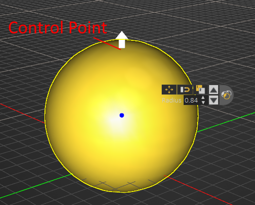
After creating a basic shape, selecting the shape will show its Control Points which appear in white. Picking on one of these points will change it into an arrow that can be pulled to update the size of the basic shape, as shown in the image below.
Paths

Create Path
Paths created in SimLab Composer/Studio can be from points in 3D space or on a plane. So when clicking the Create Path option, the Path Creation dialog will open, for the user to pick 3D or planer path.
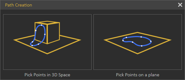
Picking points in 3D space will create a path that is not on one plane. This can be useful to create a path for geometry to follow, or path for camera.
Picking points on a plane, requires specifying the plane to create the path on. The path and all selected points will be on this plane.
Both path creation options will open the Path Creation dialog shown below, where the user can create different types of paths.

The user can select Linear Path, B-Spline Path, Arc Path, or switch between the types to have a line segment for example following a B-Spline Path.
Paths can be open or closed, clicking on the first point in the path will close the path.
Apply Tangents
One of the points of a created path should be selected, before choosing this option. The program will ask for picking a point and normal to determine the tangent. So picking a point will modify the location of the picked path point to become tangent to the selected point.
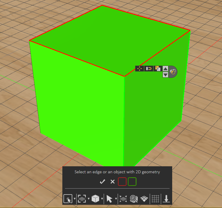
Generate From 2D
Creates 2D path from the outline of a selected surface. Using the Select options from the Common Tool bar can help in selecting a face, like selecting Pick Edge Loop, as shown in the image below.
Feature
Features created in SimLab Composer/Studio allow the user to perform basic modifications and improvements to 3D models in order to improve the realism of the 3D scene without needing to revert to a CAD application.

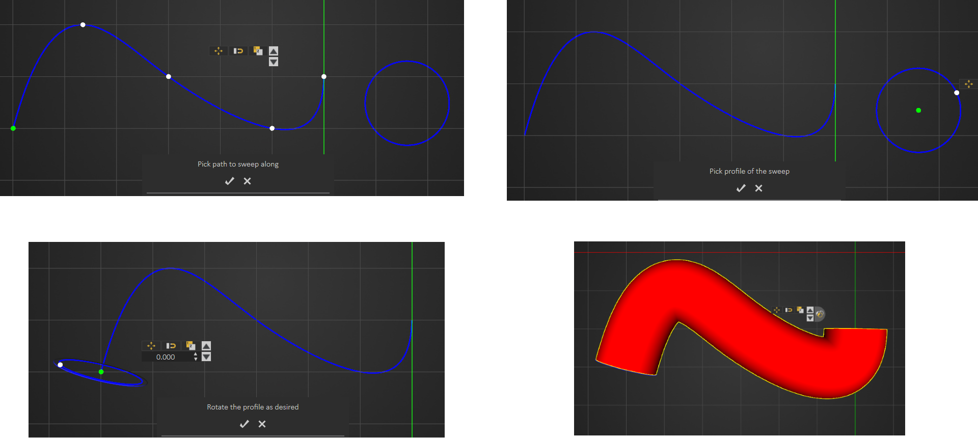
Sweep
This feature enables users to extrude a shape along a created path. After creating the path and shape, select Sweep form the menu, and start by picking the path to sweep along as the message indicates. Next, select the profile to sweep, and rotate the profile as desired then click to create sweep.
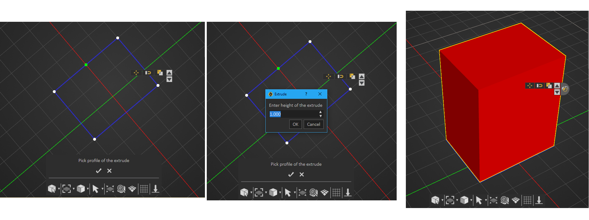
Extrude
Create a closed 2D shape, then in the extrude window enter the height, and a 3D object will be created. If an open 2D shape is used the created model will be hollow.
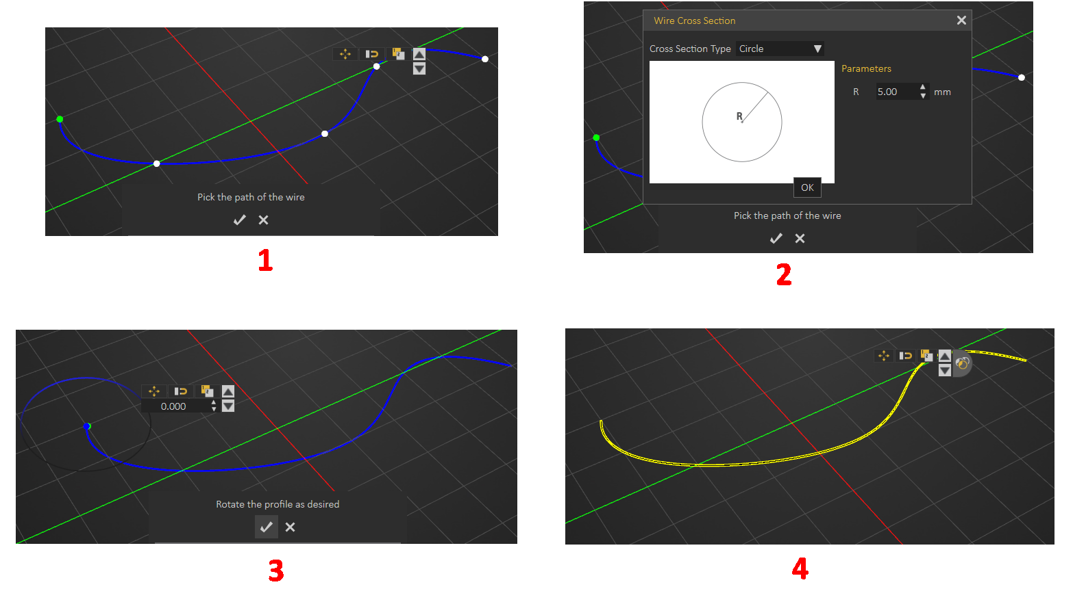
 Wire
Wire
A path should be created first for the wire to follow, then the steps are as shown below. Check this tutorial on how to create wires.
Street
SimLab Composer's Street creation tool expands design capabilities effortlessly and efficiently.
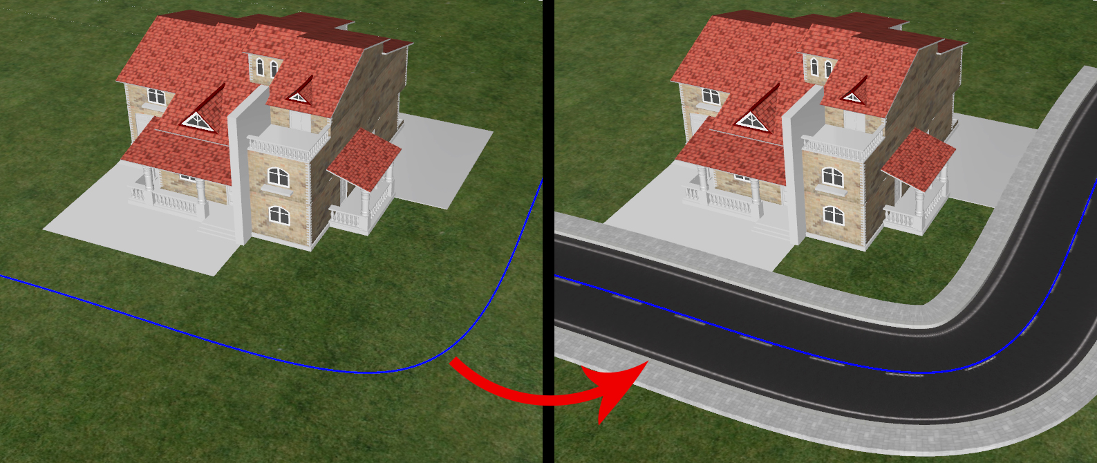
- Create a path for the street to follow
- Select the path then select Street under Features from the Create menu

- Select the type of street from the available options
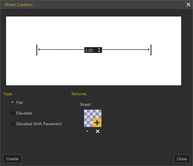

4. Select texture for street and pavement once you click on (+) in the textures side of the window.

5. Click Create and the street will appear in the 3D area and will be added to the Objects Tree
Annotations
Adding annotations and measurements to 3D scenes in SimLab Composer, can create a professional presentation that facilitates communicating and sharing a design.
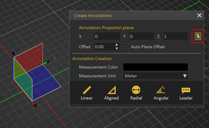
Upon selecting this option, 3D plane selection will appear to select the the plane on which to create the annotations. If it did not appear click on the Pick button highlighted in the image below.
Selecting the proper plane for the annotations creation is crucial in terms of where the annotations will be projected for viewing. You also have the option to offset the plane you have selected parallel to its axes. Measurement units can be changed in the dialog below.
Several types of annotations can be created.
- Linear, measures the projected width between two points and not the distance between them.
- Aligned, measures the distance between two points in space without projecting their location on a principal axes
- Radial, measures radial distance of 3D object.
- Angular, measures the angle between two intersecting lines.
- Leader, adds custom text with a pointer to the design.
Bounding Box Group
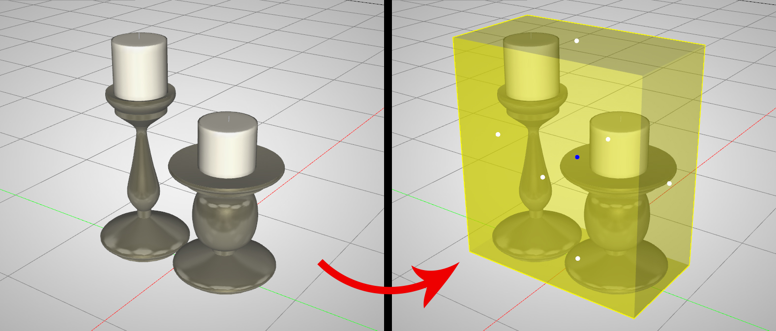
Creates a ghost box for a single selected object or a group of objects. The ghost box can then be used in a Boolean operation to modify the geometry of objects. Select an object or group of objects, then click select Bounding Box form the Create menu. The Bounding Box will appear and will be added to the Objects Tree.
Camera
Creates a camera in the 3D area and adds it to the Scene Browser. All necessary functions for creating, and setting the different cameras can be found in the Properties dialog when the camera is selected.

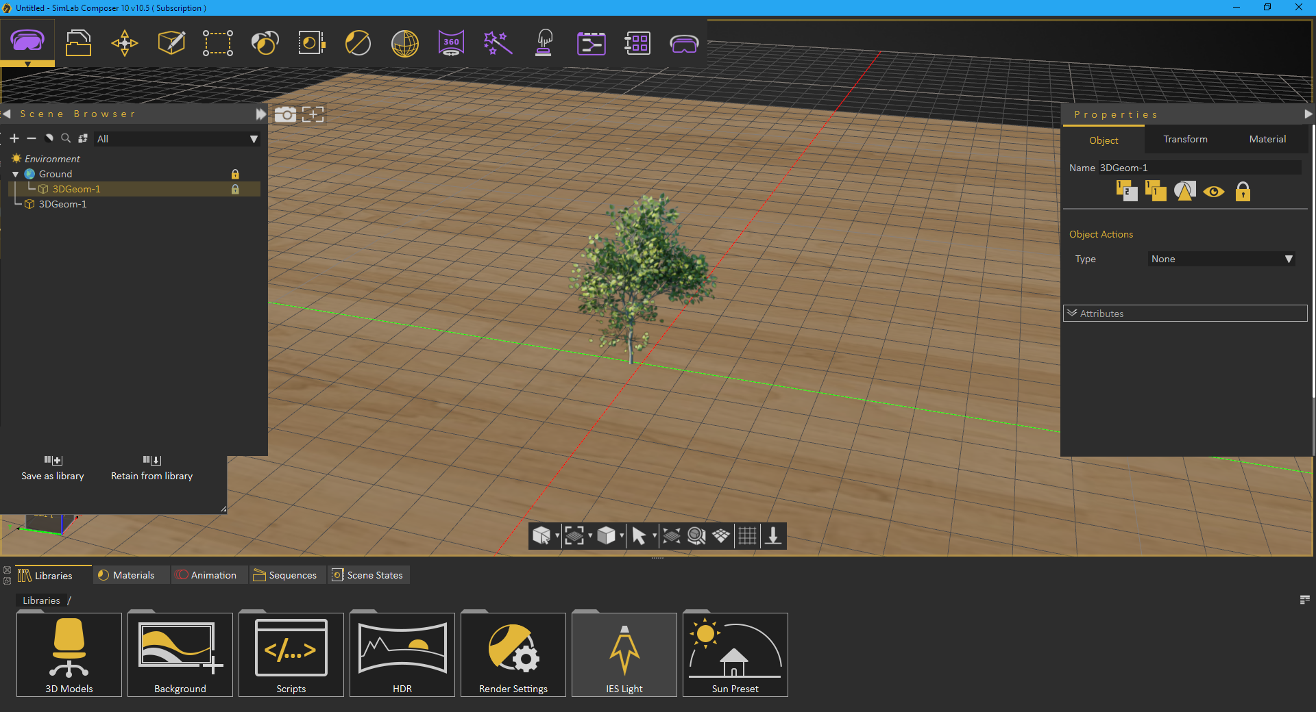
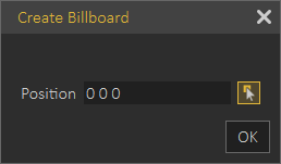
Billboard
Creates geometry that will be always aligned to the current camera. The plane geometry linked to the Billboard will rotate around the local Z axis to face the viewer at all times.
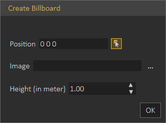
To create a Billboard, select Billboard from the Create menu, click anywhere in the 3D area to pick a position (X, Y, Z) to place the billboard at. Browse and select an image (choose PNG image format to preserve transparency). The default image will be a tree if the user didn't select an image. Enter the suitable height in meters, it takes the aspect ratio of the selected image, the width of the Billboard will be approximated automatically.
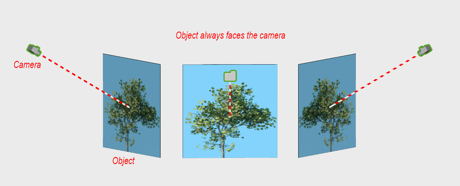
The billboard object always faces the camera, to allow architects to add PNG trees and humans to the scene.
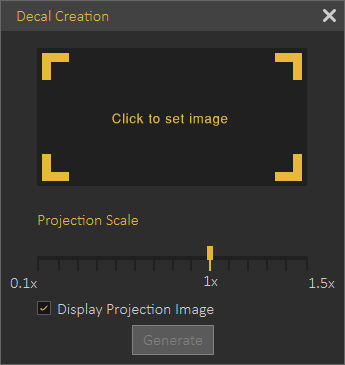
Decal
Applying a company logo, or product images to 3D models is made easier with Decal Creation from the Create menu. The parameters in the Decal window are:
- Image: Requires setting a valid path for a valid image file.
- Projection Scale: Uniform scale value applied to the decal image.
- Display Projection Image: Check box which if checked will display selected image for easier application.
To learn more about decal creation, check this tutorial, and this article
Text
2D Text
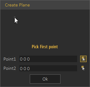
Used to create 2D text, that can be formatted as in any other text editor, as shown in the dialog below. This 2D text can be saved as a *.png Image that can be used to create Decal.

A plane can be created by picking two points, in the dialog below, and the 2D text will be attached to it.
Finally the 2D text can be added as a Billboard by selecting a position for it in the dialog shown below.
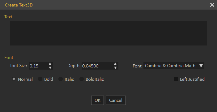
3D Text
In the Create Text3D dialog, the user can type in text, and select its format. Clicking OK will create 3D text parallel to the ground at the center of the 3D area. An assembly with geometry for all letters in the text will be added to the Scene Browser, and different transforms can be applied to the 3D text. A user can also change the material of the generated 3D Text, by dragging material form the materials library, and dropping it on its geometry in the Scene Browser.
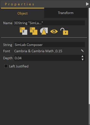
To modify anything in the created 3D text, select the text in the 3D area, or from the Scene Browser, to display its properties in the Properties Panel.
Section Plane
Section plane will be created and selected in the 3D area with the 3D dragger to enable the user to transform/rotate the section plane. Section plane effects are exported to file formats such as OBJ.
By default a section plane cuts through the whole scene. Using the Break By Section Plane tool in the Geometry menu, the user can select the geometry to cut using the section plane(s).
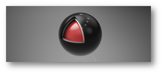
In the image shown below a scene with three spheres inside each other and three section planes were created with different orientations. Select each section plane and use it to cut through the outside and the middle spheres. To do that go to Geometry menu and with the sphere to cut being selected, select Break by Section Plane function. This will break the geometry into two in the Scene Browser and the 3D area.
Repeating this for all three section planes will split each sphere into eight parts. Deleting/ hiding some of the parts will result in the shown image.
Geometry Menu
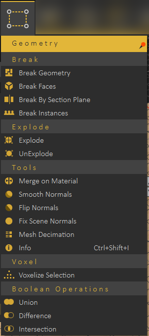
Break Group
Break Geometry
The smallest representation of geometry in SimLab Composer is 3D Geom, which is a geometry that has one transform and one material applied to it. All contents of 3D Geom are moved together, and have the same material.
Some model formats do not support saving Scene Browser structure, so when importing 3D models of those formats, 3D Geom can contain many none connected parts. The Break Geometry tool enables the user to break a 3D Geom that contains none connected parts into multiple 3D Geoms. Each one of the new 3D Geoms can be moved separately and can be assigned a unique material.
Break Faces
In case the Break Geometry tool fails, Break Faces will break the selected 3D model into its faces. Each face will be converted to 3D Geom, and added to the Scene Browser. Unique materials can be assigned to each face.
Break by Section Plane
A section plane should be created first in the scene, using Section Plane function in the Create menu. This function requires/enables the user to select the geometry to cut through. Using the same section plane with different orientations, different cuts can be done on the geometry.
Break Instances
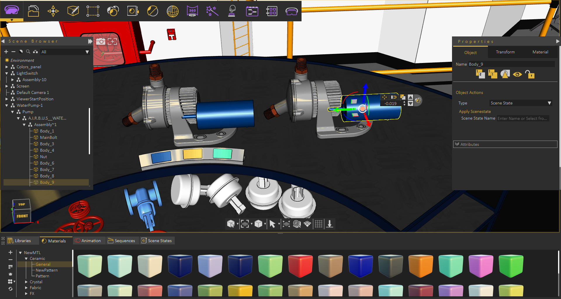
Instances in SimLab Composer are multiple duplicates of an object using the same materials structure, and same transforms as the original object. Instances are created by selecting an object then clicking Ctrl+t. In the below image a second water pump was created as an instance of the original one, thus they share the same material.
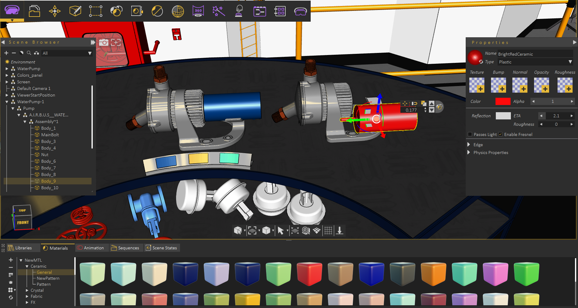
Using Break Instances each pump can now have its own materials/transforms.
Explode Group
Explode / UnExplode
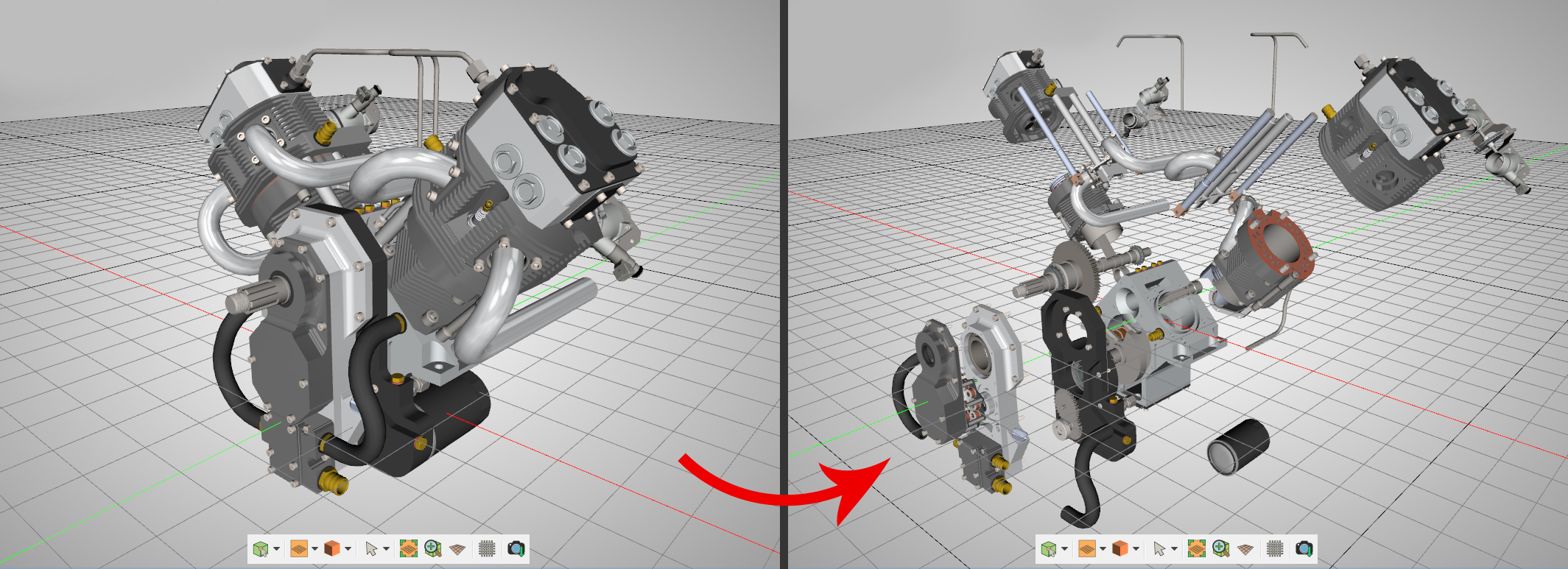
Can be used to show the components of an assembly. Selecting it will show geometry draggers, allowing the user to move (explode) the selected object(s) in the X, Y, and Z directions. The user can also rotate the dragger to select an arbitrary vector to be used for exploding the assembly. Check this tutorial for more about Explode function.
The user should click either the Approve or the Decline mark in In the central part of 3D area, when done with exploding the geometry. Clicking the red Decline mark will cancel the operation of creating the exploded view. After completing the explode operation the user can go back to the original model by selecting UnExplode.
Tools Group
Merge on Material
With an assembly selected in the 3D area, selecting this tool will merge geometry using the same material into a single geometry.
Smooth Normals
This tool can be used to average the normals of the geometry to appear smoother during rendering. Also vertices having the same position and normal direction will be replaced by a single vertex, thus reduce the size and complexity of a 3D model.
Flip Normals
Clicking this tool will have the selected objects' normals flipped.
Fix Scene Normal
Generates appropriate normals for the selected geometry.
Mesh Decimation
Reduces the number of polygons in the selected geometry without affecting its appearance greatly.
The following tutorial shows Mesh Decimation in action, The tool can be very helpful if you need to run VR experience on memory limited devices
Info
Clicking this tool will display Geometrical Info dialog, showing the number of objects, vertices, and polygons in the selected geometry. Knowing the number of vertices and polygons can help a user estimate the size of the output file. This might make the user ignore some details, for sharing efficiency. Shortcut (Ctrl + Shift + I)
Voxel Group
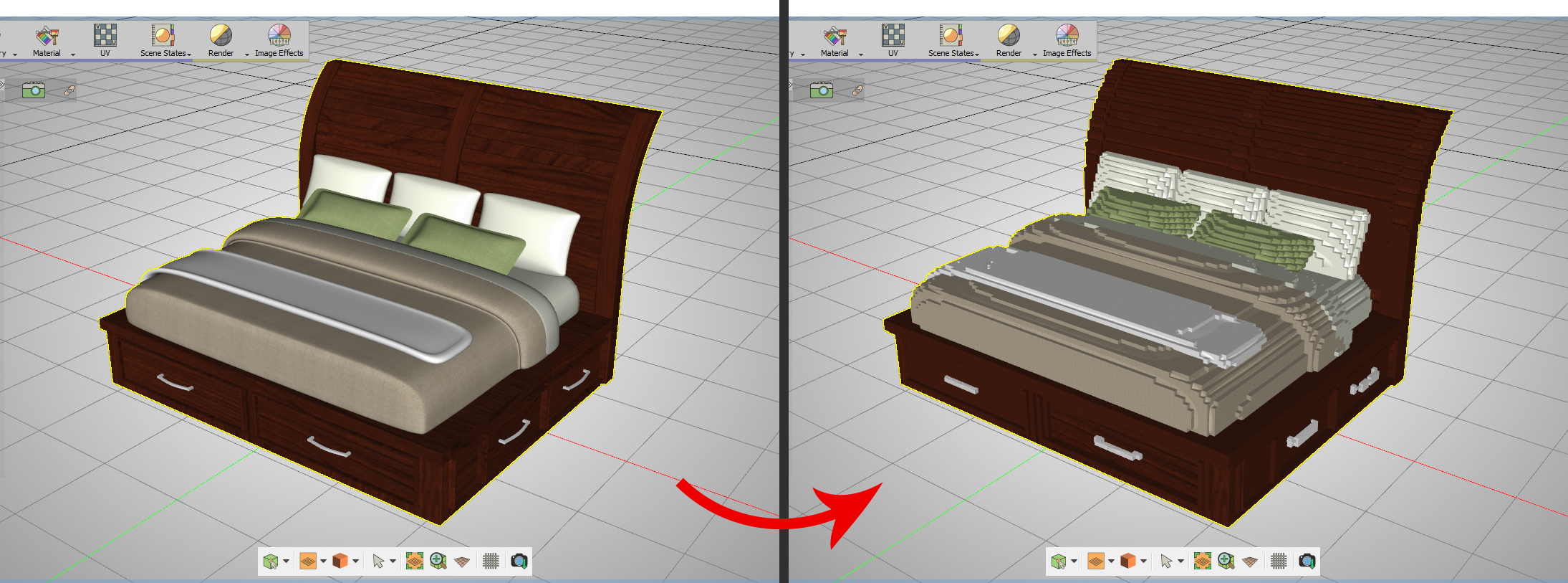
Voxelize Selection
Voxelizing a 3D model is rebuilding the 3D model using building blocks (voxels), like LEGO. The user can choose the building block to use for voxelization, and can choose to voxelize the whole scene, or the selected geometry. Notice that this will add a significant number of polygons to the 3D scene.
The Voxelize Options dialog will open, when selecting this options. The default voxel object is a cube of certain size, and the user can choose a different object shape, by clicking the Pick voxel option. The voxel object needs to be a geometry in the scene, and the user can just pick it.
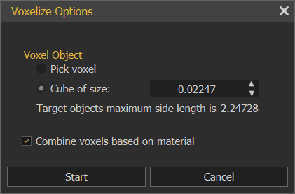
The Combine voxels based on material option, if checked, will combine all voxels, based on material, each in one geometry in the Scene Browser.
If not checked each voxel will have its own geometry in the Scene Browser.
To Voxelize any 3d model, follow the steps below:
- First, export 3D model from any 3d software as one of the Supported Import Formats in Composer
- Import your model to Composer, click File → Import, or by using Ctrl+I, then select your model format and click Open.
- Select the 3D model in SimLab Composer and click on Geometry → Voxelize Selection. The Voxelize Options dialog will appear, where the default voxel object is a cube of certain size. The smaller the size of the voxel the larger the size of the output file. The user can choose a different object by clicking the Pick voxel option then select another small object eg, Sphere, Cylinder or any object in the scene, then click Start.
- When the convert operation is complete, the new object will be added to the Scene Browser.
Boolean Operations Group
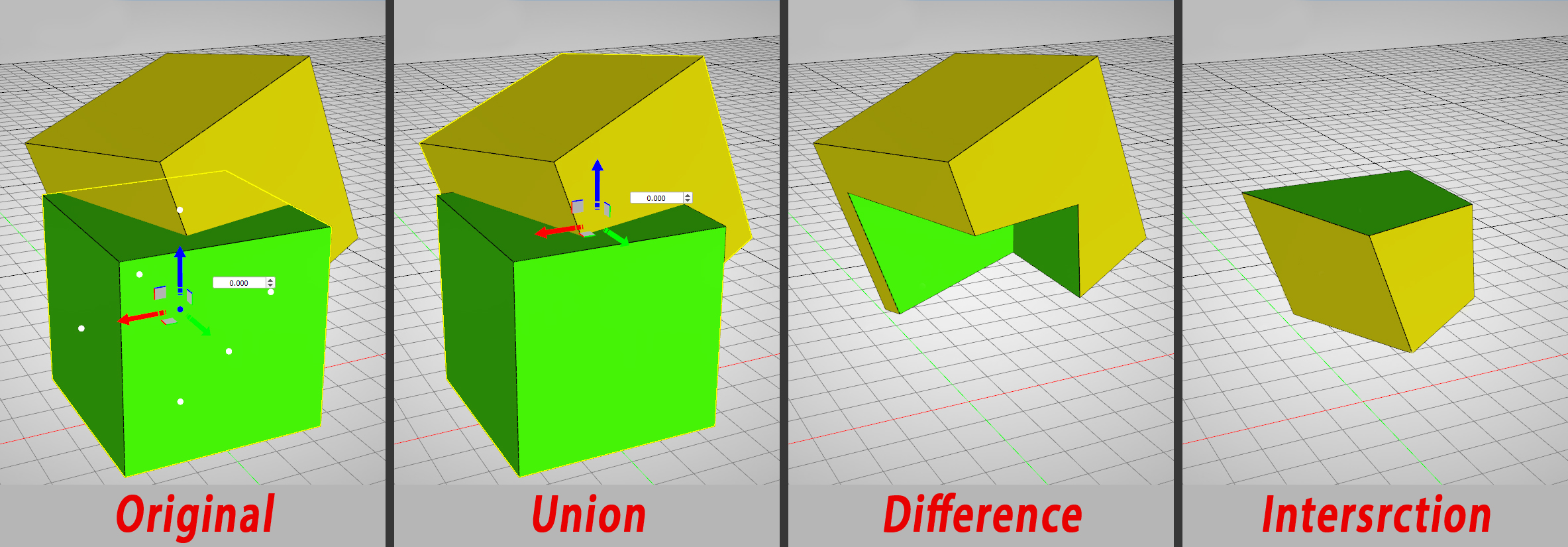
Boolean Operations
Boolean operations are smart tools that ease the process of performing simple modeling tasks in SimLab Composer and without the need to go back to the CAD design application.
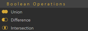
- Union: Removes the intersecting part of two objects or set of objects, and preserves the remaining as one.
- Difference: Deducts the shape and volume of one object or set of objects from another object or set of objects. So it's like the first 3D object minus the second.
- Intersection: Preserves the intersecting part of two objects or set of objects, and removes the rest.
Material Menu
Includes all the functions needed for material application, and materials management. Check this tutorial for more about material management.

Scene Group
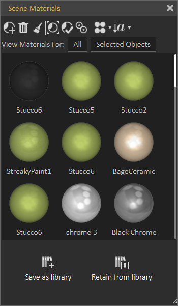
Manage Scene Materials
Scene Materials dialog includes the material functions shown in the image below. It shows all materials in the scene where the user can make changes to all of them at once.
- Add Material: Adds a new default material to the list. The new material with all of its properties will be shown in the Properties Panel of the application Interface.
- Delete Material: Deletes the selected material, from the list. In case the material is being used by objects in the scene, a dialog will appear asking the user to select a replacement material before the deletion.
- Delete Unused Materials: Deletes all materials not referenced by any object in the scene.
- Select Objects Using Material: This function selects all objects, in the scene using the selected material in the Scene Materials dialog. These objects-geometry will be highlighted in the Scene Browser, and in the 3D area.
- Apply Material To Selected Objects: To use this function the user should select object(s) first, then select a material from the Scene Materials dialog or the from the Material Library. After that he can click this function button and the selected material will be applied to the selected objects.
- Merge Identical Materials: In cases where more than one object in the 3D scene are using the same material, different copies of that material will appear in the Scene Materials window. This function cleans the materials dialog from unnecessary duplicates.
- Change View: This display option is available for the user to change the way the materials are displayed, in the Scene Materials dialog. They can be displayed as Large, or Small icons, or can be shown as a list.
- Sort by Name/Sort by Attributes: Two options for sorting the Scene Materials are available for the user.
Save as Library
After applying all materials for all geometry in a 3D scene, clicking this function will display the New Material Library window. In this window the user can input a name for the new library then click Ok. This will save the applied scene materials in a library, and it will be shown in the Current Library combo-box, and in the Manage Material Libraries panel.
Retain from Library
Before clicking this function button, the user should select the material library to use, in the Current Library combo-box. This function will reapply materials included in the selected library to the different geometry based on previously assigned materials names.
Merge Identical Materials
Cleans Scene Materials dialog from unnecessary duplicates.
Material Palette Group
Save Material Palette
Material palette is a useful feature that SimLab Composer provides, it can save materials progress in a separate external file that can be re-applied easily.
From the material menu select Save Material Palette. Set the path and name for the file and click Save.
Reopen CAD Software and load the saved file, then from the extension menu, go to SimLab Composer integration and select Link with SimLab Composer.
As you can see the materials and textures applied in SimLab Composer, are the same materials applied in CAD Software.
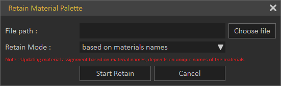
Retain Material Palette
This function allows the user to keep applied materials in SimLab Composer to the design. Not having this option toggled will re-import the original materials from CAD Software to the design.
Select the palette file that you previously save, and set the mode to material name
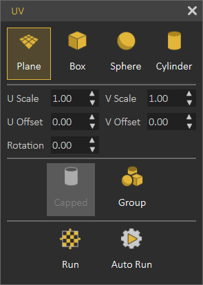
UV
Texturing is the process of applying an image to 3D object, to give it a more realistic look. Texture Coordinate menu gives the user different options to define the way the image is applied to an object.
Scene States Menu
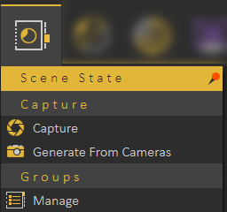
Capture
Enables the user to capture different configurations for the selected 3D model(s) (Object Properties), or useful properties for the whole scene (Scene properties). The user can check the properties to include in a scene state.
SimLab Composer and Studio's Scene States are smart in capturing attributes, they can include any combination of the listed attributes. This can be helpful in creating scene states for models with different attributes, and setups.
Scene States may include a combination of:
- Position/Transform
- Material
- Visibility
- Lighting
- Environment
- Current View (Camera)

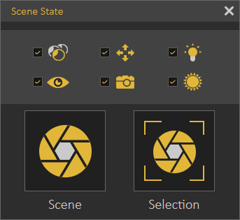
After selecting what to include in the Scene State, the user needs to click Capture to capture the scene state. Captured scene states are added to the Scene States Library.
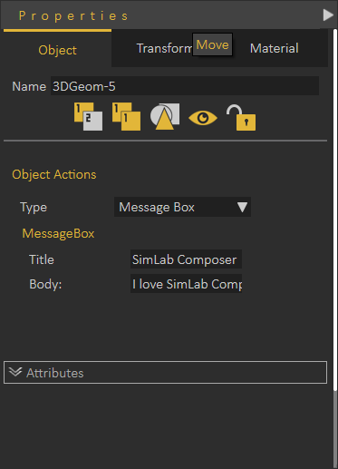
Scene States can be applied as Object Actions in the Properties dialog. Apply Scene State can also be used as a response in Training Builder
The following tutorial shows how to use Scene States:
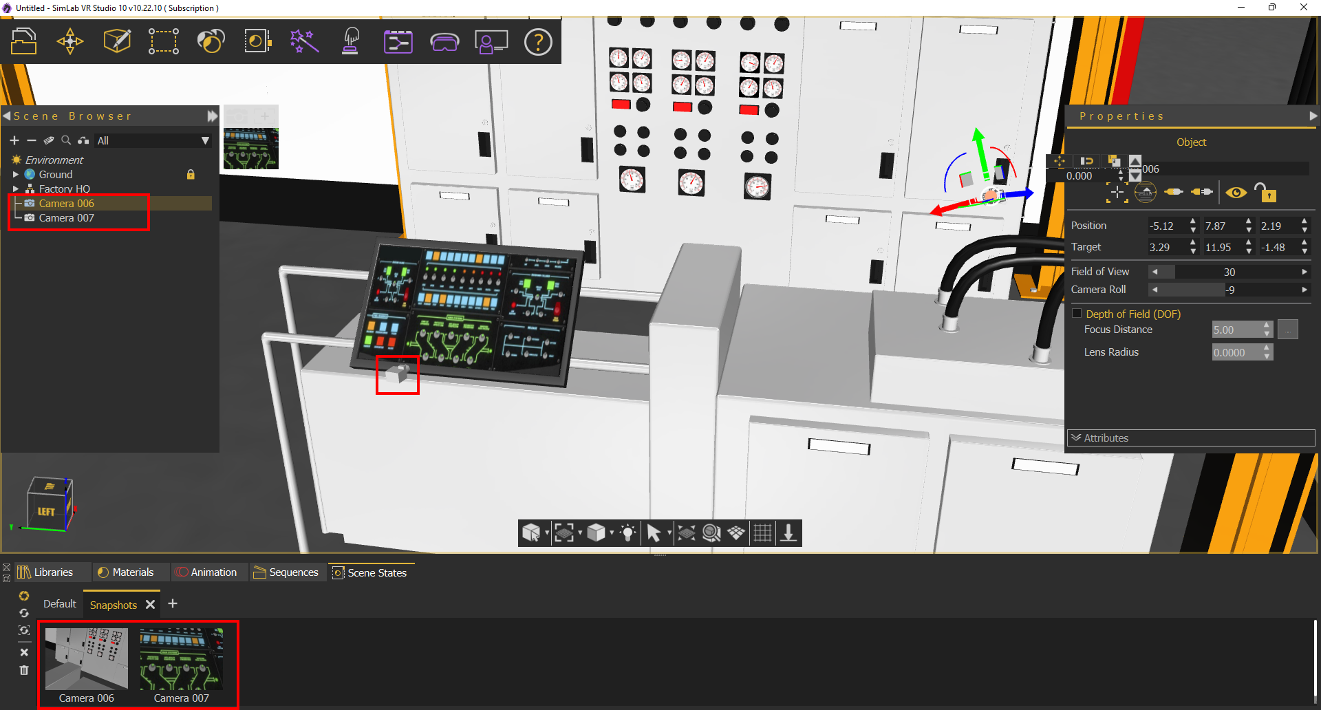
Generate From Cameras
Captures scene states from the created cameras in the scene, as shown in the image below:
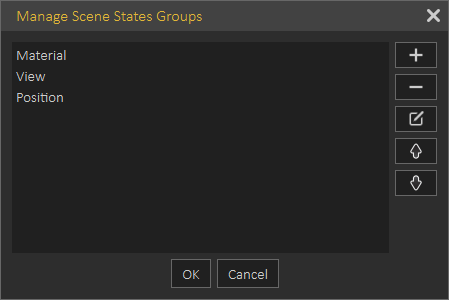
Manage
Opens Manage Scene States Groups dialog box, where the user can add a new group, remove, rename, or reorder groups.
When creating a new Scene State it will be automatically added to the active group tab in the Scene State Library.
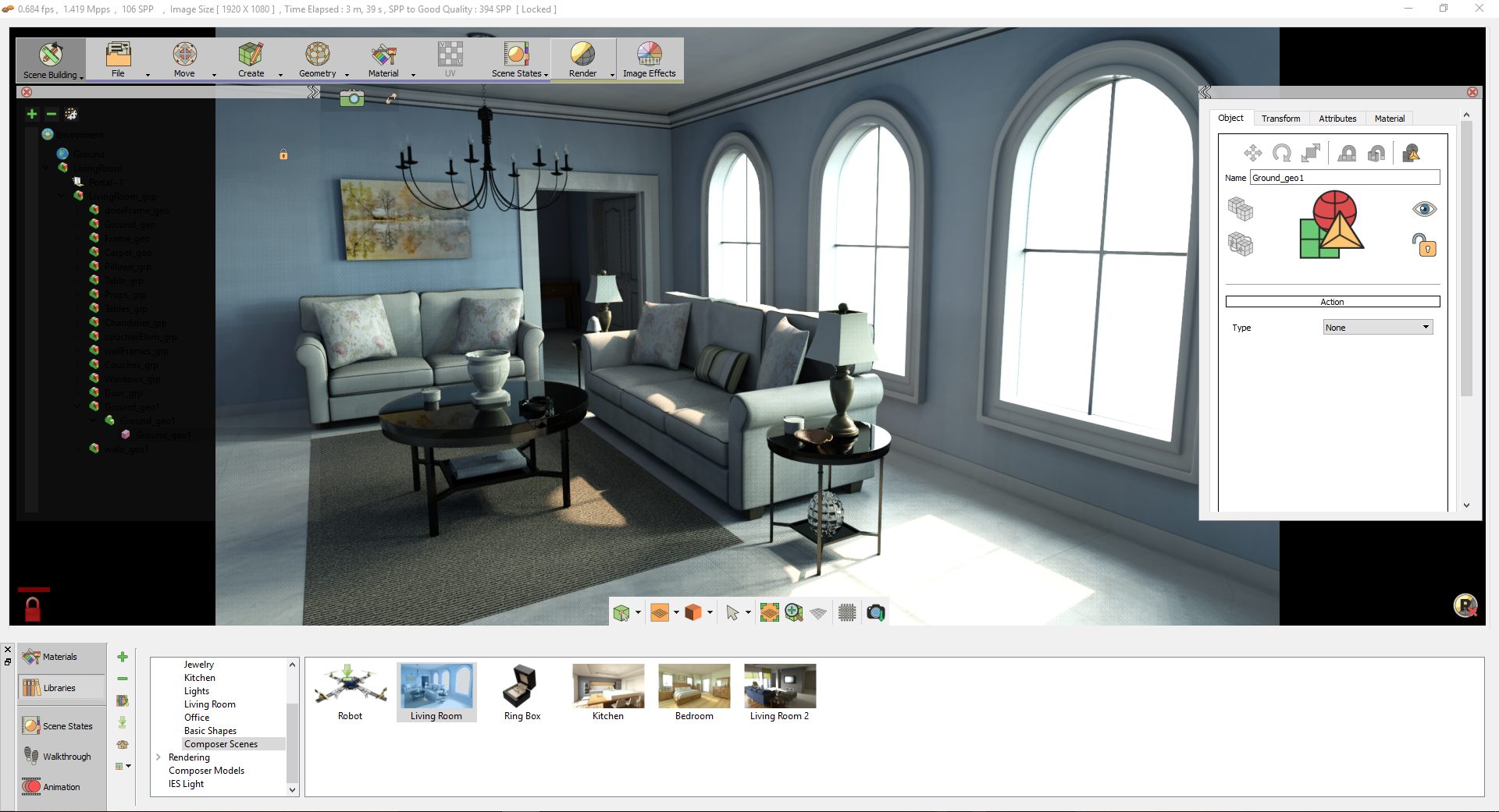
Render Menu
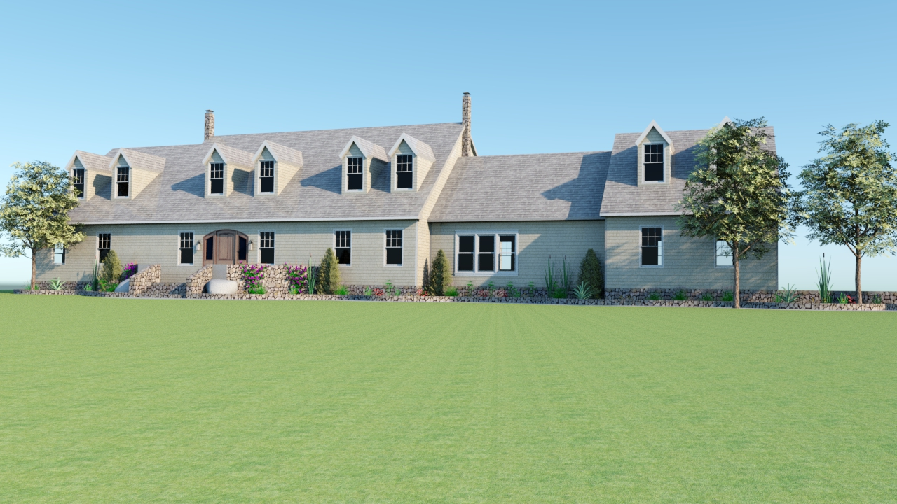
SimLab Composer Real-Time renderer (SimLab RT) is a powerful, fast, and easy-to-use real-time renderer; that has full integration with SimLab Composer. The renderer is optimally parallelized, so it can take advantage of all the CPUs available in the machine.
SimLab RT renderer is suitable for MCAD, interior rendering, and producing top-quality rendered images. To learn more about SimLab RT renderer, click Help in the Setting/Help menu, and select Render Help.

In the tutorial video below, we will show you how to import a 3D model to SimLab Composer, then shows how to assign materials, After that the tutorial teaches how to utilize the rendering capabilities of SimLab Composer.
Render Group
Real-Time
Starts real-time rendering for the 3D scene, using the parameters in Render Settings. The function short-cut is F4, and RT rendering can be stopped by un-toggling the Real Time function button or pressing F4.
Fixed
This function starts real-time rendering for the 3D scene, with a fixed image size. The image size used will be the one set in the Output Image task.
To File
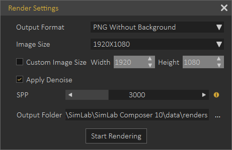
Check this SimLab Rendering Basics tutorial.
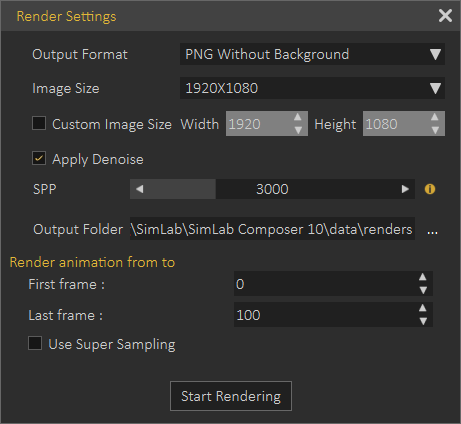
Multiple Frames
Animation
3D scenes with animation defined, clicking the Animation function will start rendering animation. Animation rendering is a limited-time rendering, from the First Frame to the Last Frame set in the corresponding spin boxes.

Render Animation in VR Viewer
Rendering is a complex process that generates realistic images, rendered images in many cases cannot be distinguished from photos. Performing complex rendering consumes a significant amount of time.
Users interested in previewing their work quickly can use VR-based rendering that gives users great images in a very short time. It is useful for multi-iterations until the user is ready for the final animation render.
The only difference in the Render Settings dialog here is the added Use Super Sampling option.
Sun Study
This is useful for landscape designers, architects, and interior designers, where the user defines the initial and final sun states.
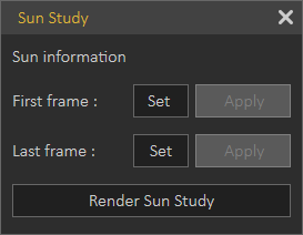
The study shows the sun and shadow states for the scene.
Scene States
For 3D scenes with scene states, this function will start consecutive rendering for the scene states defined in the scene. After setting the parameters in the Render Settings dialog and clicking Start Rendering, the Manage Scene States dialog will appear for the user to check the scene states to render, and the order of rendering. Clicking Ok will start limited-time rendering based on the SPP value.
VR-based animation rendering demo video.
Package
Distribute
Distribute rendering is supported in SimLab Composer. It allows the user to distribute the rendering of complex animations, among a number of machines. With the animation ‘*.sim’ file opened click Distribute function to open Distribute Render Animation dialog.

Fill in the required settings, and then click the Generate Rendering Packages button. The output folder containing the packages will open since the Open containing folder option was checked in the dialog.

A number of (*.srd) files equivalent to the number of machines input in the dialog, will be saved in the output folder.
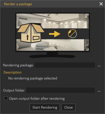
Copy each file to a rendering machine that has SimLab Composer already installed. Click the Render function, in the Package group, to open its dialog. Browse to the rendering package (*.srd) file, and select the output folder. Check the Open output folder option, and then click Start Rendering. A rendering animation progress bar will continue to appear along with rendering menus until the animation rendering is done.
Settings Group
Image Effects
SimLab Composer provides its users with image post-processing capabilities, where any combination of image effects can be applied to a rendered image. In this task, the Tree/Task panel will display the Render Settings for the image.
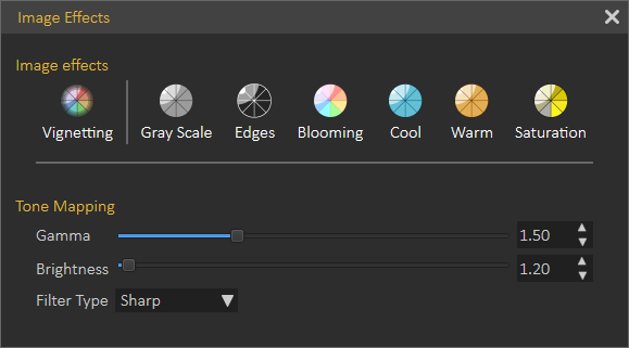
Vignetting
Reduces image brightness/saturation, at the periphery of the image compared to its center.
Gray Scale
This effect renders the image in grayscale.
Edges
This effect renders the current model with the edges shown.
Blooming
A glow was added to the rendered image. The user can change the Blur Radius, Brightness, and Opacity for this effect.
Cool, Warm and Saturation
These image effects can be applied by setting a delta value, and they can be applied exclusively.
Output Settings
In this dialog tab, the user can select the format for the output image and its dimensions. The user can also input the base file name, the output folder, and SPP to limit the rendering. The open containing folder check option will open the output folder after finishing rendering.
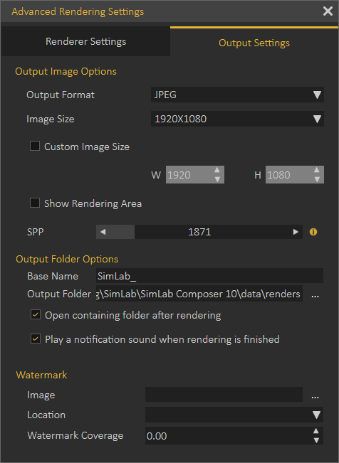
Advanced Render Settings
In this panel, the user can set the main rendering parameters.
- Rendering modes: where the user can select from available types of rendering modes:
- Fast Path Tracer.
- MIS Path Tracer.
- Interior Renderer.
- Element Renderer.
- Light Depth: Set the amount of light energy.
- Specular Depth: Control the visual appearance of specular reflections. It represents the amount of specular reflectivity a surface has.
- Automatic locking Time (seconds); is the time in seconds after which the image will be locked for navigation, in case of Real-Time View rendering. Setting this value to Zero will disable automatic locking.
- The number of CPU cores to be ignored; is the number of CPU cores not used by the renderer. This is helpful when the user is working on other applications while rendering. Setting this parameter to 0 will use all cores for rendering.
- Navigation speed while rendering;

The default values for both Light Depth and Specular Depth (which is "3") are good and commonly used. Don't change this unless you really know what you're doing.
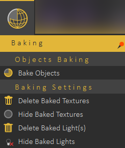
Baking Menu
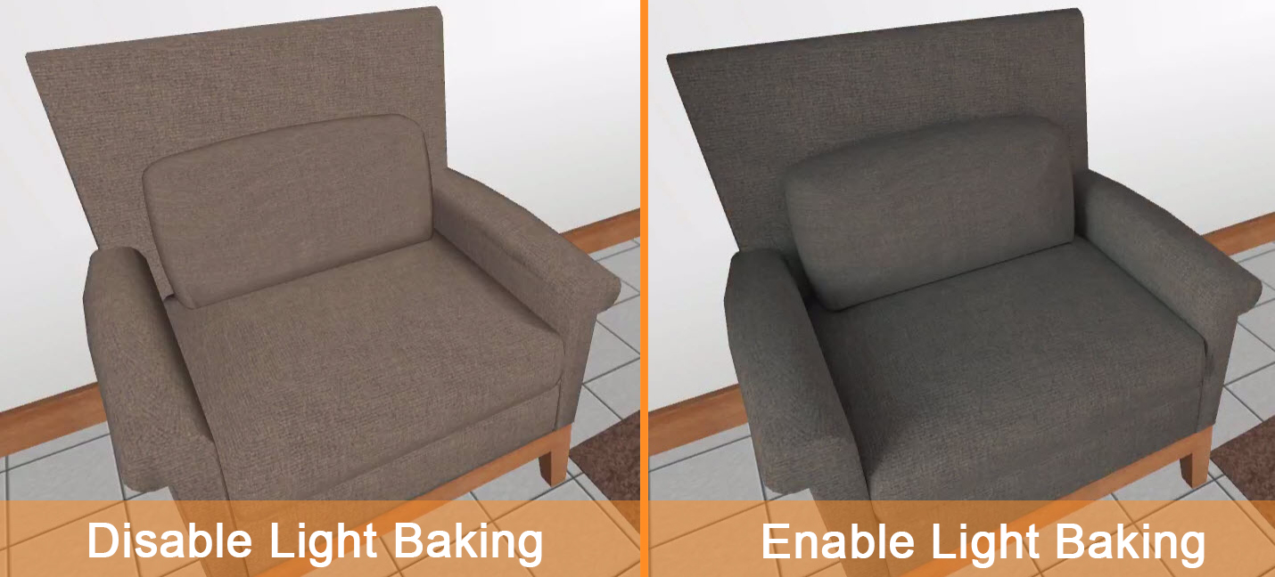
Baking is a technology that stores lighting and shadow information within objects, and away from their materials. It means that a user can change the material and/or modify its properties even change its texture without the need to bake it again and again.
The image below shows the difference between enabling and disabling light baking.
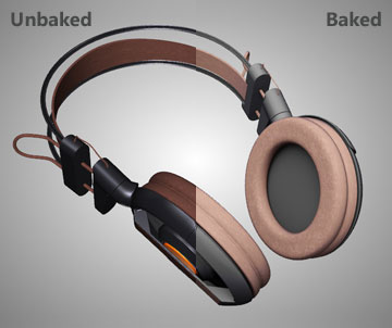
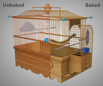
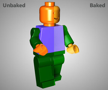
Using Light baking for superior Mobile VR
The user can switch between the two to experience day and night views by using Sunlight or interior IES lights in the VR scene.
Bake Objects
Texture baking/Light backing is the process of storing rendering results as textures/lights.

Basics of Texture Baking video tutorial:
**By clicking the Smart Bake button, the Texture Baking Setting dialog box appears (as shown in the following image), the following options can be found in the Texture Baking Setting dialog box:
Texture Size
Baking Quality
- Sample Per Pixel (SPP): controls the quality of the texture baking.
- Dynamic Update (in SPP): controls at which rate should the texture baking results appear during the baking process.
- Geometry Processing: fast or Top Quality
Optimize Baking Time
Polygons Per Object Limit: enter the limit number for polygons per object.
To learn more about Texture/Light backing refer to this tutorial.
Help Menu

News
Starting with News, where a dialog will be displayed including latest news regarding the application, and its updates.
Check for Updates
Check for Updates, as the name implies, will display the dialog with the latest release of the application.
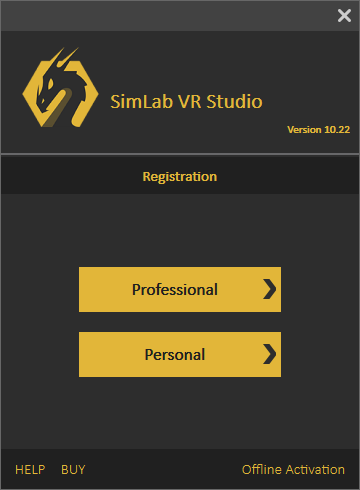
License
License, displays the Registration dialog, where the user can request to start a free personal license, request a trial license, or activate a professional license. More information about Composer licensing process can be found here
Cloud License

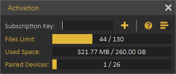
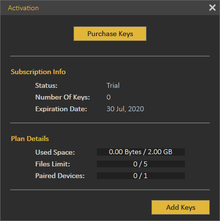
Cloud license option allows the user to do the following:
- View current cloud account status
- Number of models uploaded
- Used cloud space
- Number of paired devices
- Add additional cloud keys to increase cloud account capacity or to extend its period.
Note: Professional software key received when ordering a license of Composer is also a valid Cloud Key, so the user can use it to activate the Cloud account. All what the user needs to do is register a Cloud account then to add the key.
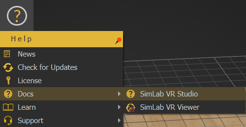
Docs
This option provides users with a list of help links available for SimLab Composer. Including a link to this help document, and a link for more information about SimLab Composer.
Learn
Learn option directs users to learning resources for SimLab Composer.
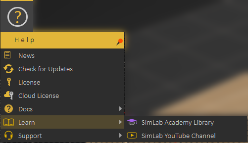
SimLab Academy displays SimLab Academy in SimLab Composer library, More information about SimLab Academy can be found here.
SimLab YouTube Channel direct the user to the corresponding site.
Support

- Report an issue
- Provide a Suggestion
- Get access to SimLab's Discord VR Community server
- Schedule a meeting
- View Blog
- View the FAQs